MI AO API
REVISION HISTORY
| Revision No. | Description |
Date |
|---|---|---|
| 3.50 | 12/04/2020 | |
| 3.51 | 07/19/2021 | |
| 08/25/2021 | ||
| 3.52 | 09/08/2021 | |
| 12/29/2021 | ||
| 3.53 | 02/17/2022 | |
| 3.54 | 03/29/2022 | |
| 05/19/2022 | ||
| 04/12/2023 |
1. OVERVIEW
1.1. Module Description
Audio Output (AO) is mainly used to configure and enable Audio Output devices, write audio data, and adjust volume.
1.2. Audio Codec Block Diagram
1.2.1. Muffin series
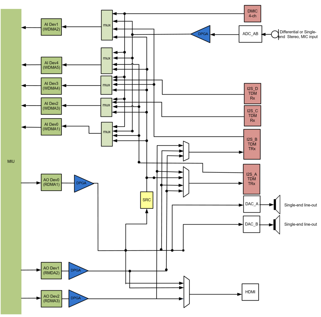
Figure 1‑1: Muffin series chips
The audio codec of Muffin series chips has the following resources:
-
WDMA * 5
-
RDMA * 3
-
DMIC interface (support 4Chn DMIC signal) * 1
-
ADC (support 2Chn Amic/Linein) * 2
-
I2S-TDM RX * 4
-
I2S-TDM TX * 2
-
DAC (support 2Chn Lineout) * 2
-
SRC * 1
-
HDMI TX * 1
1.2.2. Mochi series
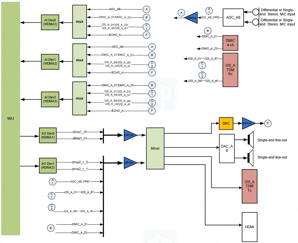
Figure 1‑2: Mochi series chips
The audio codec of Mochi series chips has the following resources:
-
WDMA * 3
-
RDMA * 2
-
DMIC interface (support 4Chn DMIC signal) * 1
-
ADC (support 2Chn Amic/Linein) * 2
-
I2S-TDM RX (16 slot) * 1
-
I2S-TDM TX (16 slot, but there are only two channels of valid data) * 1
-
DAC (support 2Chn Lineout) * 2
-
SRC * 1
-
HDMI TX * 1
1.2.3. Maruko series
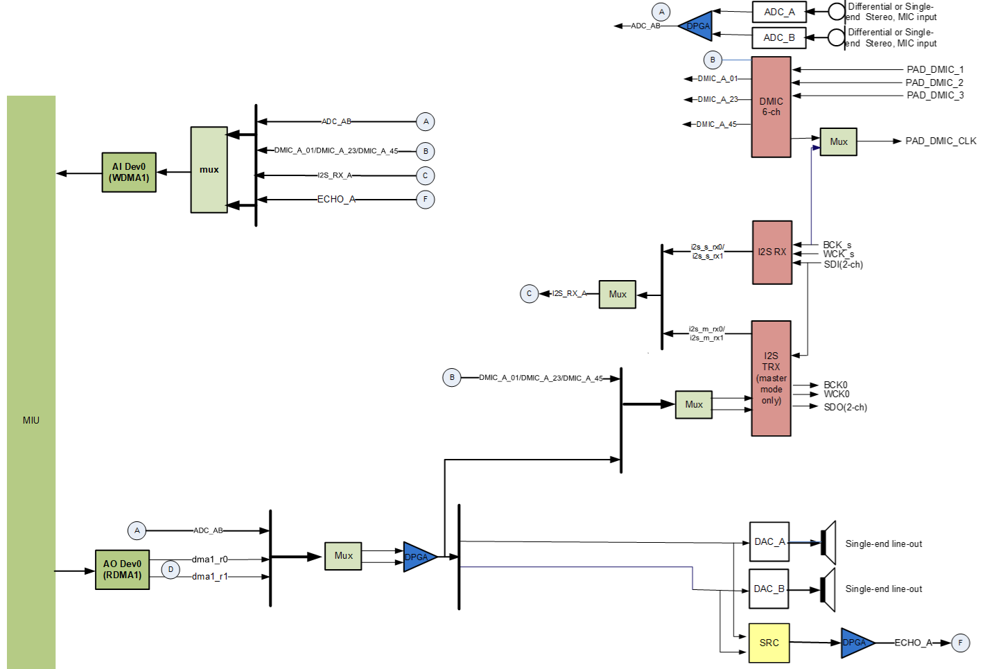
Figure 1-3: Maruko series chips
The audio codec of Maruko series chips has the following resources:
-
WDMA * 1
-
RDMA * 1
-
DMIC interface (support 6Chn DMIC signal) * 1
-
ADC (support 2Chn Amic/Linein) * 2
-
I2S RX(2 slot) * 2
-
I2S TX(2 slot) * 1
-
DAC (support 2Chn Lineout) * 2
-
SRC * 1
1.3. Audio Codec
-
DMA
Direct Memory Access, DMA transfer copies data from one address space to another address space, and provides high-speed data transfer between peripherals and memory or between memory and memory. When the CPU initializes this transfer action, the transfer action itself is realized and completed by the DMA controller. The DMA transmission method does not require the CPU to directly control the transmission, and there is no interrupt processing method to retain the scene and restore the scene process. The hardware opens a channel for direct data transmission for RAM and IO devices, which greatly improves the efficiency of the CPU.
-
WDMA
Direct Memory Access Writer.
-
RDMA
Direct Memory Access Reader.
-
MUX
MUX is the multiplexer data selector. In the process of multiplexing data transmission, any circuit that can be multiplexed out according to needs. The Mux in front of WDMA selects multiple data sources for WDMA, which can support the selection of ½/4 data sources (the data sources can be the same or different). Each data source has two channels, that is, the selection of 2/4/8 channels data is written to DRAM by WDMA, which acts as a multiplexer. However, the Mux, which is close to the output peripheral interface (such as I2S TX/HDMI/DAC, etc.), realizes the function of selecting one.
-
DPGA
Digital Programmable Gain Amplifier, is a very versatile amplifier, and its amplification factor can be controlled by a program as needed.
-
DMIC
Digital Microphone Interface, audio codec only provides DMIC interface, not a complete DMIC. The DMIC interface provides the clock signal required for DMIC work, and receives the PDM signal from the DMIC.
-
ADC
Analog Digital Conversion, the electronic component that convert analog signals into digital signals.
-
I2S
Inter-IC Sound integrated circuit built-in audio bus, is a bus standard developed by Philips for audio data transmission between digital audio devices. Sigmastar's I2S bus only supports the standard I2S data format and the left-justified I2S data format. At the same time, it also supports TDM (Time-Division Multiplexing) technology, which interleaves different signals in different time periods and transmits them along the same channel, which can support 4/8 channel data transmission.
-
DAC
Digital Analog Conversion, the electronic component that convert digital signals into analog signals.
-
SRC
Sample Rate Convert.
-
HDMI
High Definition Multimedia Interface, AO output interface, is a fully digital video and sound transmission interface, which can transmit uncompressed audio and video signals.
-
Mixer
Mixer, hardware mixing, using the linear superposition averaging algorithm (if the volume of a certain channel of audio is particularly low, the volume of the entire mixing result will be lowered), and the output sampling rate can be set after mixing.
1.4. Audio Codec Difference Description
1.4.1. Muffin series
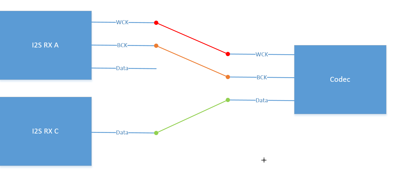
Muffin series chips have I2S RX * 4, but I2S RX C and I2S RX D have two modes, one is called share mode and the other is called slave mode. In share mode, I2S RX C and I2S RX A share I2S Clock (Wck and Bck), and I2S RX D and I2S RX B share I2S Clock (Wck and Bck). When both I2S RX A and I2S RX C need to be used at the same time The I2S parameters of the I2S must be completely consistent. The Codec that is connected to the I2S RX C needs to connect the I2S Clock pins (Wck and Bck) to the I2S Clock (Wck and Bck) of the I2S RX A, and the Data pin to the Data of the I2S RX C. Then, the hardware solution is shown in the figure below. Slave mode, I2S RX C and I2S RX D have independent clocks, but they can only be used as slaves. These two modes can be set by i2s-rx-mode under the dts sound node, 0 is slave mode, and 1 is share mode.
1.4.2. Mochi series
The audio codec of Mochi series chips has the following resources: WDMA * 3, RDMA * 2, DMIC interface (support 4Chn DMIC signal) * 1, ADC (support 2Chn Amic/Linein) * 2, I2S-TDM RX(16 slot) * 1, I2S-TDM TX(16 slot) * 1, DAC (support 2Chn Lineout) * 2, SRC * 1, HDMI TX * 1.
The Mochi series chip I2S supports a maximum of 16 slots, and the sampling rate is newly added to support 96K/192K. Note: In the usage scenario of I2S, the maximum I2S BCK cannot exceed 30MHz (eg: BCK=16bit * 16slots * 192K=49.152M or BCK=32bit * 16slots * 192K=98.304M, the usage of BCK > 30MHz is not supported).
It supports mixing of two AO devices, represented by Mixer in the Audio Codec block diagram. After mixing, you can set the output sampling rate to 8K/16K/32K/48K (not supported yet).Supports separate mixing of two physical channels, represented by Mixer in the Audio Codec block diagram, and the output sampling rate after mixing supports 8K/16K/32K/48K (not supported yet).
Note: ADC_AB_PRE in the Audio Codec block diagram of Mochi series chip represents the audio signal before DPGA, as shown in Figure 1-2.
1.4.3. Maruko series
Maruko series chips, although there are two sets of I2S RX, but two sets of I2S RX cannot be used at the same time. Here are two sets of I2S RX usage scenarios:
I2S RX:
-
External codec transmits non-I2S signals, which need to be adjusted to Wck and Bck, such as receiving PCM signals.
-
Need to synchronize with Dmic Share clock to achieve Dmic and I2S RX.
-
External codec works in master mode.
I2S TRX:
- Need to use I2S TX.
The I2S RX is selected by using the i2s-pcm under the dts sound node. 1 is I2S RX and 0 is I2S TRX. In addition, whether I2S RX and Dmic share clock are configured through dmic-bck-share. 1 is the share clock, and 0 is the independent clock.
1.5. Keyword
-
Device (Audio ouput device)
AO device refers to the RDMA of the audio codec. Device is an abstraction of DMA in audio codec by audio3.0. RDMA in audio codec and AO Device have a one-to-one correspondence. For example, AO Device0 corresponds to RDMA1 in audio codec, AO Device1 corresponds to RDMA2 in audio codec, and so on. The data streams of audio3.0 are all connected in series with DMA as the center.
Audio3.0 also includes another type of Device, that is, AI devices directly send data streams to AO devices without DMA, such as (Amic→Lineout). This type of device is called a direct device, that is, Passthrough, and currently only supports MI_AUDIO_PASSTHROUGH_DEV_1.
-
Interface (Audio output peripherals)
AO Interface is an abstraction of audio ouput peripheral interfaces in audio codec, such as Speaker/I2S Codec/HDMI interfaces.
-
Attach
AO attach refers to attaching Interface to RDMA. For AO Device, Attach is to connect the output signal of RDMA to a specific Interface, so that the peripheral can output audio signals. AO Device supports dynamic Attach.
When the same AO Interface is attached to two AO Devices, the output of the AO Interface is the result of the output of the two AO Devices mixing (supported by Mochi series).
When the use scene contains Passthrough, you need to attach AI first, then attach AO, otherwise it will not work normally.
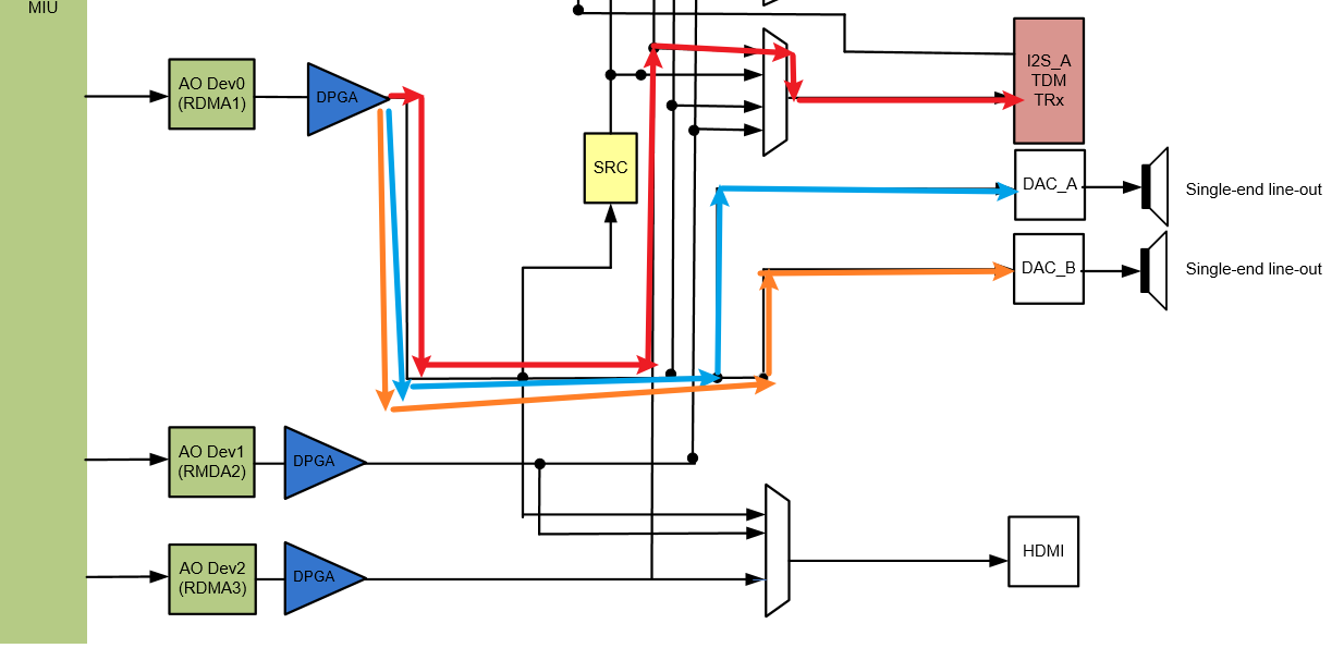
The following figure is the result of attaching I2S TX and DAC0/1 to RDMA1. After the signal output from RDMA1 is adjusted by DPGA for gain adjustment, it is divided into 3 branches to reach DAC0, DAC1 and I2S TX respectively. The Attach of Ao Device is setting the flow direction of these branches.
-
Detach
Disconnecting Interface with RDMA.
-
Echo
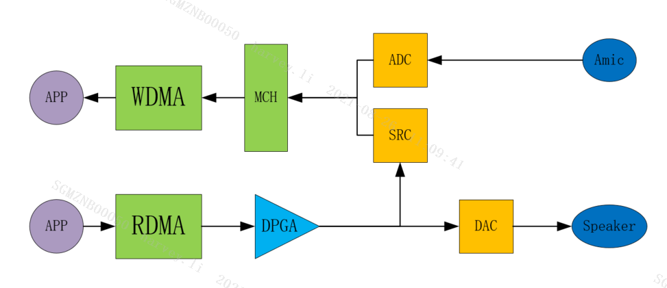
The Echo of AO refers to the reference data of AEC. It can be seen from the audio codec block diagram that the input of SRC is the signal output by RDMA and amplified by DPGA, and the output of SRC is the signal after re-sampling the input, which can be sent to WDMA through Multi Channel as the echo reference data of the AEC algorithm. .
For AI Device, Echo represents the output signal of SRC in the audio codec block diagram. For AO Device, Echo means to connect the output of AO Device to the input of SRC. The following figure shows a simple block diagram of the data flow of AI Device and AO Device using Echo at the same time. The application can obtain the aligned AEC far end and near end data.
-
Sound Mode
AO Sound Mode refers to the audio channels, such as mono and stereo.
-
Channel Mode (Channel output mode)
Support static setting and dynamic setting of Channel Mode. Currently Muffin series chips not support dynamic Channel Mode setting.
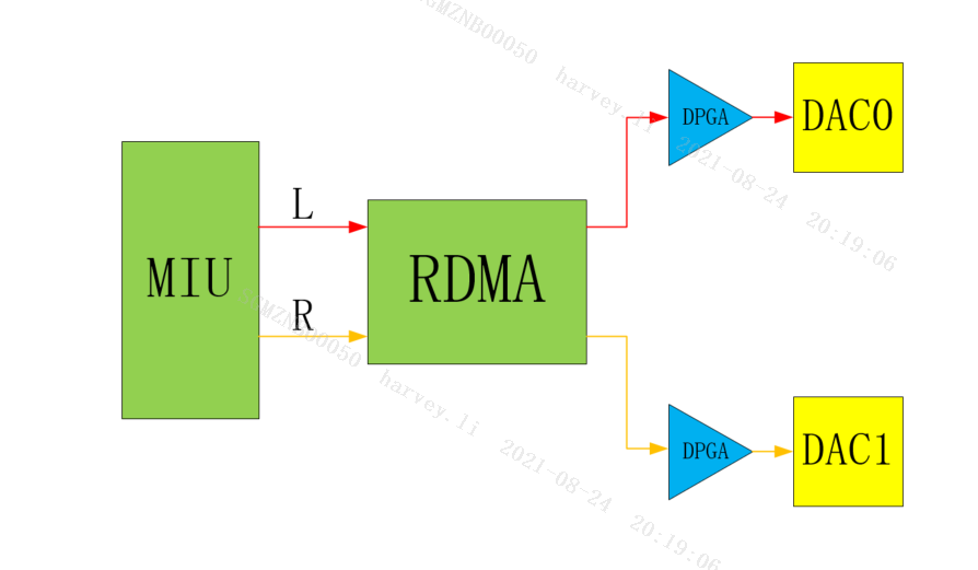
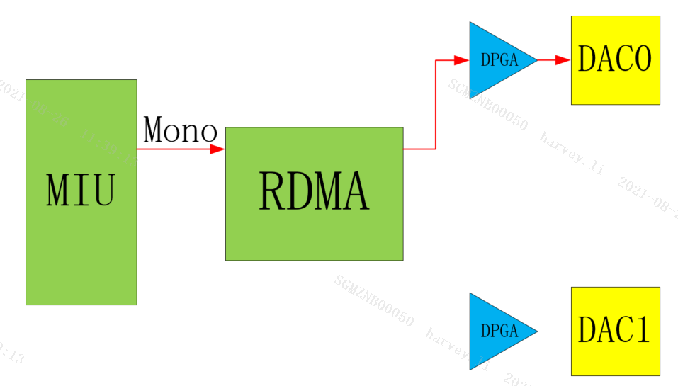
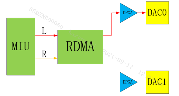
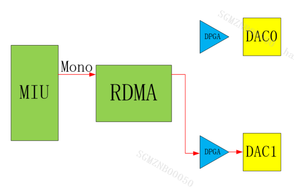
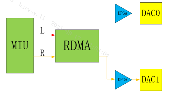
AO Channel Mode refers to the output mode of the RDMA channel. For AO Device, Channel Mode determines the corresponding relationship between the audio channel of the audio data and the left and right channels of the Interface output. The following illustrates the role of Channel Mode in conjunction with the diagram.
-
E_MI_AO_CHANNEL_MODE_STEREO
Normal stereo mode.
-
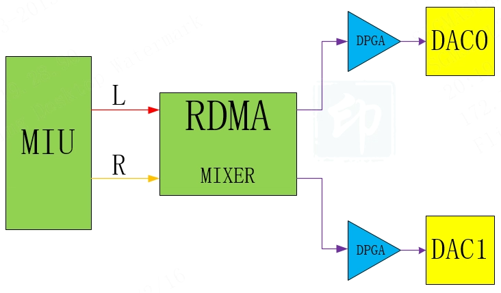
E_MI_AO_CHANNEL_MODE_DOUBLE_MONO
Double Mono mono, the left and right channel output the same mono data.
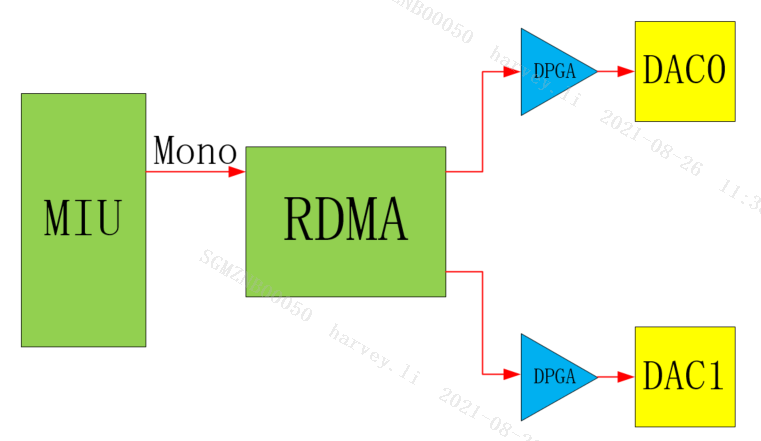
Double Mono stereo, the left and right channel output left and right channel mixed data. (Muffin series chips not supported).
-
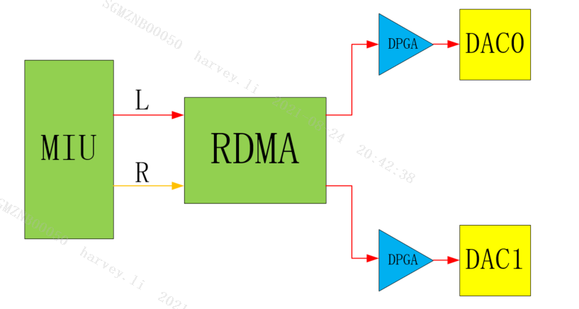
E_MI_AO_CHANNEL_MODE_DOUBLE_LEFT
Double Left stereo, the left and right channel output left channel data (Muffin series chips not supported).
-
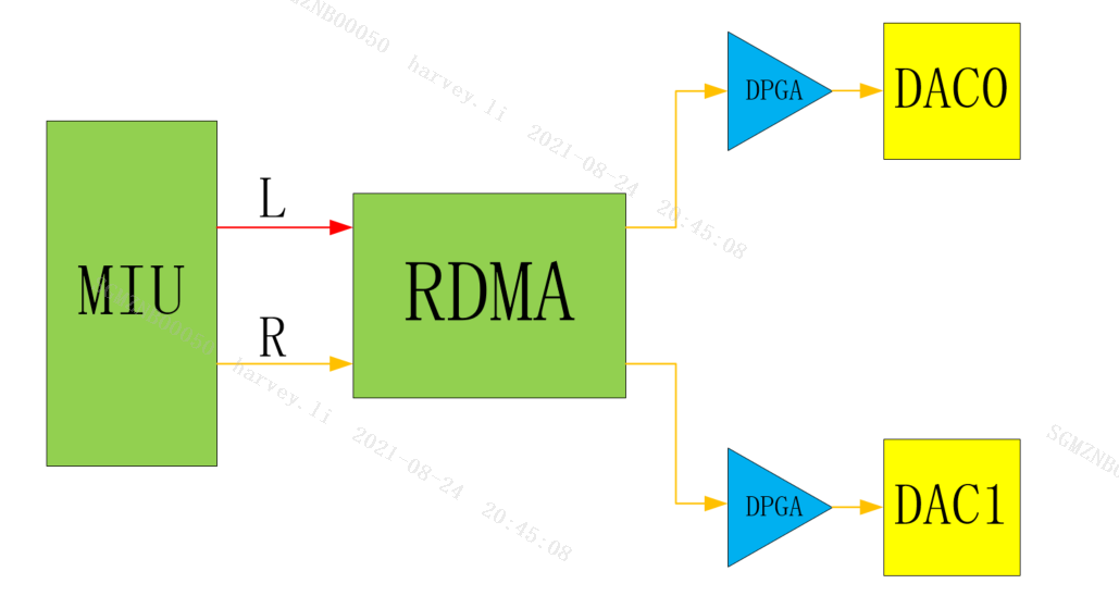
E_MI_AO_CHANNEL_MODE_DOUBLE_RIGHT
Double Right stereo, the left and right channel output right channel data (Muffin series chips not supported).
-
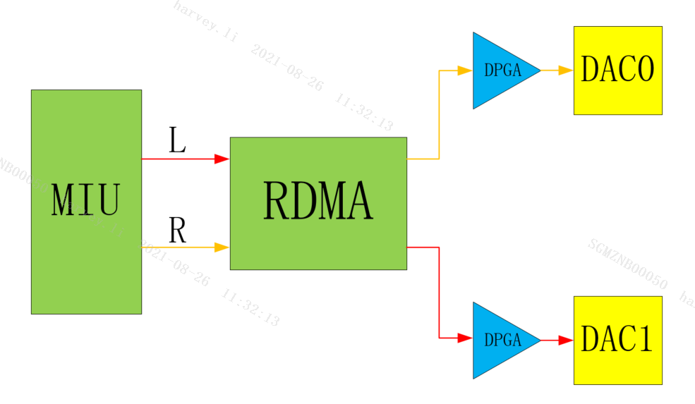
E_MI_AO_CHANNEL_MODE_EXCHANGE
Exchange stereo, the left and right channel output left and right channel exchange data.
-
E_MI_AO_CHANNEL_MODE_ONLY_LEFT
Only Left mono, only the left channel output mono data.
Only Left stereo, only the left channel output stereo data.
-
E_MI_AO_CHANNEL_MODE_ONLY_RIGHT
Only Right mono, only the right channel output mono data.
Only Right stereo, only the right channel output stereo data.
-
-
Gain
AO Gain is divided into two categories in the audio3.0 architecture, one is the DPGA Gain associated with the Device, that is, the DPGA in the audio codec block diagram, and the other is the Gain unique to Interface. For AO, gain can only be adjusted through Dpga at present.
-
Format
What data format is used to represent an audio sample. Currently, only S16_LE format (PCM Linear 16bit (Little Endian)) is supported.
-
Sample Rate
Sample Rate, that is, the playback sample rate.
-
Period Size
For AO Device, Period Size represents the default starting condition of AO Device (only when the number of samples in the buffer is greater than the Period Size, the device will start).
-
I2S parameter
-
I2S Mode
I2S Mode determines the working mode of I2S, whether it is standard I2S mode or Tdm I2S mode (2Channel or multi-channel), Master or Slave (Master provides synchronous clock, Slave receives synchronous clock). Generally speaking, there are no restrictions on the working mode, as long as it can match the external Codec clock.
-
I2S BitWidth
The bit width of I2S sending and receiving data, currently support 16/32bit, but the hardware can only process 16bit, which means that when the bit width is 32bit, the lower 16bit is invalid data.
-
I2S Format
I2S Format is the alignment of I2S. Currently, only I2S Philips and Left-justified alignment are supported. The following figure shows the waveforms of these two formats.
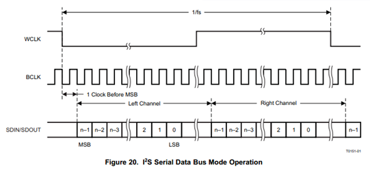
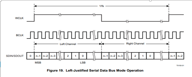
I2S Philips alignment format, the first data bit of the sample data appears after the first BCLK (serial clock) of the WCLK (left and right channel switching clock) transition. In the left-aligned format, the first data bit of the sample data appears in the first BCLK (serial clock) of the WCLK (left and right channel switching clock) transition, and the polarity of WCLK is opposite to the alignment format of I2S Philips.
-
I2S Sample Rate
The sample frequency of I2S transmission and reception.
-
Mclk
Mclk, called the master clock, also called the system clock (System Clock), is generally 256 or 384 times the sample rate. The function is to enable better synchronization between systems, but it is not necessary. Currently only 12.288M, 16.384M, 18.432M, 24.576M, 24M, 48M, etc. are supported.
-
bSyncClock/4-Wire/6-Wire Mode
There are two wiring methods for SigmaStar's I2S. One is the 4-Wire mode, including RX_WCK, RX_BCK, RX_SDI, TX_SDO four wires. In this mode, TX does not have an independent clock, and all clocks are provided by RX. Therefore, in this mode, TX needs to rely on RX to use. TX cannot be used alone, and the parameters of I2S TX must be consistent with I2S RX. The other is 6-Wire mode, including RX_WCK, RX_BCK, RX_SDI, TX_WCK, TX_BCK, TX_SDO six wires. In this mode, RX and TX are independent and not related. The choice of 4-Wire/6-Wire Mode needs to be decided according to specific scenarios.
If bSyncClock in the MI API I2S parameter is TRUE, 4-Wire Mode is used, and FALSE is 6-Wire Mode. The RX and TX belonging to the same group of I2S cannot be set to 4-Wire Mode on one side and 6-Wire Mode on the other side.
-
Slot
Slot represents the number of channels transmitted by I2S. Currently, 2 slots are supported in I2S mode, and 4/8/16 slots are supported in Tdm mode.
-
-
Passthrough
Passthrough refers to the channel that directly sends the data stream from the AI device to the AO device without DMA. Take ADC_AB→DAC_AB as an example, the red marked path in Figure 1-3 below:
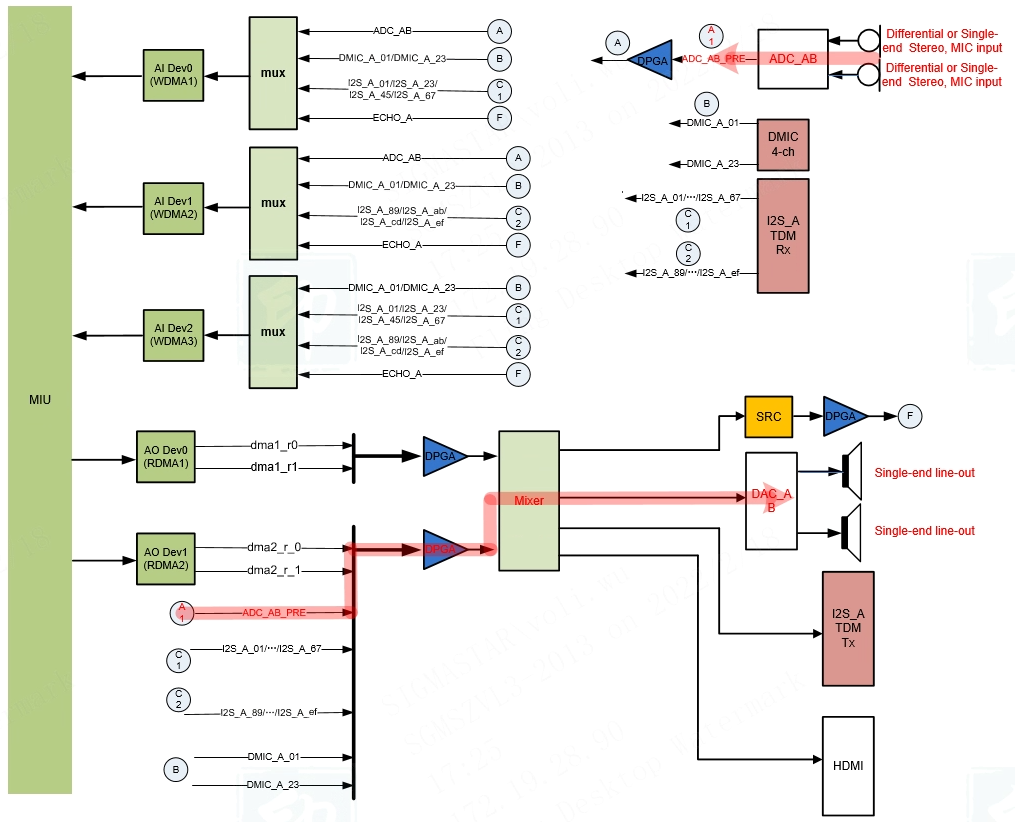
Figure 1-3: Mochi series chip passthrough diagram
Muffin series chips only support Passthrough from ADC_AB as input device to DAC_AB as output device.
Mochi series chips support any combination passthrough from ADC_AB/DMIC_A_01/ DMIC_A_23/I2S_A_01/…/ I2S_A_EF as input device to DAC_AB/I2S_TX/HDMI as output device. The current Passthrough limitations of Mochi series chips are: only support 48K sampling rate; Passthrough Device does not support Channel Mode setting; in Passthrough + DMA mixing scenarios, the output device only supports DAC_AB.
2. API REFERENCE
Audio output (AO) is mainly used to enable audio output devices, send audio frames to output channels and other functions.
| API name | Features |
|---|---|
| MI_AO_Open | Open audio output device |
| MI_AO_OpenWithCfgFile | Open the audio output device and initialize it according to the config file |
| MI_AO_Close | Close AO devices |
| MI_AO_AttachIf | Mount peripherals to AO device |
| MI_AO_DetachIf | Disconnect peripherals from audio output device |
| MI_AO_Write | Write audio data |
| MI_AO_Start | Start the AO device and start playing |
| MI_AO_Stop | Stop the AO device and stop playing |
| MI_AO_Pause | Pause AO device |
| MI_AO_Resume | Resume AO device |
| MI_AO_SetVolume | Set AO device volume |
| MI_AO_GetVolume | Get AO device volume |
| MI_AO_SetMute | Set AO device mute parameter |
| MI_AO_GetMute | Get AO device mute parameter |
| MI_AO_SetIfVolume | Set AO peripheral volume |
| MI_AO_GetIfVolume | Get AO peripheral volume |
| MI_AO_SetIfMute | Set AO peripheral mute parameter |
| MI_AO_GetIfMute | Get AO peripheral mute parameter |
| MI_AO_SetI2SConfig | Set I2S TX config info |
| MI_AO_GetI2SConfig | Get I2S TX config info |
| MI_AO_AdjustSpeed | Adjust the playback speed of AO device |
| MI_AO_GetTimestamp | Get the current playback timestamp and cached data volume of the AO device |
| MI_AO_GetLatency | Get the delay of AO device |
| MI_AO_InitDev | Initialize AO device |
| MI_AO_DeinitDev | De-Initialize AO device |
| MI_AO_GetAttr | Get AO device attributes |
| MI_AO_SetChannelMode | Dynamically set the channel output mode (Muffin series chips not support) |
2.1. MI_AO_Open
-
Features
Open audio output device.
-
Syntax
MI_S32 MI_AO_Open (MI_AUDIO_DEV AoDevId, const MI_AO_Attr_t *pstAttr);
-
Parameters
parameter name description Input/Output AoDevId AO device number Input pstAttr AO device attribute pointer Input -
Return Value
-
Zero: Successful
-
Non-zero: Failed, see error code for details
-
-
Requirement
-
Header files: mi_ao.h
-
Library file: libmi_ao.a/libmi_ao.so
-
-
Note
Audio output device attributes include data format, sound mode, sampling rate, Playback threshold, and channel output mode.
-
Audio data format(MI_AUDIO_Format_e)
The data format of the sampled samples. Only S16_LE is supported.
-
Audio sound mode(MI_AUDIO_SoundMode_e)
Channels of the data to be played, such as mono/stereo.
-
Audio sampling rate(MI_AUDIO_SampleRate_e)
Number of samples in one second, the higher the sampling rate, the smaller the distortion, but the amount of data processed also increases.
The 8k sampling rate is used for voice, and the 32k or higher sampling rate is used for audio.
-
Playback threshold (u32PeriodSize)
Only when the data cache meets this sample will it start playing. After this parameter is set, it is recommended to write audio data in this size. When the period size is 0, APP needs to actively call MI_AO_Start to start playing.
-
Channel output mode (MI_AO_ChannelMode_e)
It determines the output mode of the audio data in the audio device.
-
The behavior of Maruko series chip I2S TX is not affected by the MI_AO_ChannelMode_e parameter.
-
-
Example
A simple example is as follow:
1.  MI_AO_Attr_t stAoSetAttr;
2.  memset(&stAoSetAttr, 0x0, sizeof(MI_AO_Attr_t));
3.  stAoSetAttr.enFormat = E_MI_AUDIO_FORMAT_PCM_S16_LE;
4.  stAoSetAttr.enSoundMode = E_MI_AUDIO_SOUND_MODE_MONO;
5.  stAoSetAttr.enSampleRate = E_MI_AUDIO_SAMPLE_RATE_8000;
6.  stAoSetAttr.u32PeriodSize = 1024;
7.  stAoSetAttr.enChannelMode = E_MI_AO_CHANNEL_MODE_DOUBLE_MONO;
8.  ExecFunc(MI_AO_Open(AoDevId, &stAoSetAttr), MI_SUCCESS);
The detailed example is as follow:
1.  MI_AUDIO_DEV AoDevId = 0;
2.  MI_AO_Attr_t stAoSetAttr, stAoGetAttr;
3.  MI_S8 s8LeftVolume, s8RightVolume;
4.  MI_AO_GainFading_e eGainFading;
5.
6.  memset(&stAoSetAttr, 0x0, sizeof(MI_AO_Attr_t));
7.
8.  // Set the Format of AO Device to S16_LE
9.  stAoSetAttr.enFormat = E_MI_AUDIO_FORMAT_PCM_S16_LE;
10.
11. // Set the Sound Mode of AO Device to Mono
12. stAoSetAttr.enSoundMode = E_MI_AUDIO_SOUND_MODE_MONO;
13.
14. // Set the sample rate of AO Device to 8KHz
15. stAoSetAttr.enSampleRate = E_MI_AUDIO_SAMPLE_RATE_8000;
16.
17. // Set the starting condition of AO Device to 1024 sampling samples
18. stAoSetAttr.u32PeriodSize = 1024;
19.
20. // Set the Channel Mode of AO Device to Double Mono
21. stAoSetAttr.enChannelMode = E_MI_AO_CHANNEL_MODE_DOUBLE_MONO;
22.
23. // Open AO Device
24. ExecFunc(MI_AO_Open(AoDevId, &stAoSetAttr), MI_SUCCESS);
25.
26. // Get AO Device attributes
27. ExecFunc(MI_AO_GetAttr(AoDevId, &stAoGetAttr), MI_SUCCESS);
28.
29. // Attach DAC_AB to AO Device
30. ExecFunc(MI_AO_AttachIf(AoDevId, E_MI_AO_IF_DAC_AB, 0), MI_SUCCESS);
31.
32. // Dynamically set the audio channel mode to Only-Left
33. ExecFunc(MI_AO_SetChannelMode(AoDevId, E_MI_AO_CHANNEL_MODE_ONLY_LEFT), MI_SUCCESS);
34.
35. // Set Dpga Gain
36. s8LeftVolume = 0;
37. s8RightVolume = 0;
38. eGainFading = E_MI_AO_GAIN_FADING_OFF;
39. ExecFunc(MI_AO_SetVolume(AoDevId, s8LeftVolume, s8RightVolume, eGainFading), MI_SUCCESS);
40.
41. // Write data to AO Device
42. MI_AO_Write(AoDevId, u8TempBuf, s32ReadSize, 0, -1);
43.
44. // Detach DAC_AB
45. ExecFunc(MI_AO_DetachIf(AoDevId, E_MI_AO_IF_DAC_AB), MI_SUCCESS);
46.
47. // Close AO Device
48. ExecFunc(MI_AO_Close(MI_AO_DEV_1), MI_SUCCESS);
2.2. MI_AO_OpenWithCfgFile
-
Features
Open the audio output device and initialize it according to the config file.
-
Syntax
MI_S32 MI_AO_OpenWithCfgFiile(MI_AUDIO_DEV AoDevId, const char *pCfgPath);
-
Parameters
parameter name description Input/Output AoDevId AO device number Input pCfgPath Path of config file Input -
Return Value
-
Zero: Successful
-
Non-zero: Failed, see error code for details
-
-
Requirement
-
Header files: mi_ao.h
-
Library file: libmi_ao.a/libmi_ao.so
-
-
Note
-
This interface is equivalent to the combination of MI_AO_Open and MI_AO_AttachIf.
-
If the audio output device is enabled, it returns success.
-
The config file template is as follow:
1.  {
2.      "DEV":{
3.          "enFormat":0,
4.          "enSoundMode":2,
5.          "enSampleRate":8000,
6.          "u32PeriodSize":1024,
7.          "enChannelMode":0,
8.          "enAoIfs":[1,4]
9.      },
10.     "I2S_A":{
11.         "enMode":0,
12.         "enBitWidth":0,
13.         "enFormat":0,
14.         "enSampleRate":8000,
15.         "enMclk":0,
16.         "bSyncClock":0,
17.         "u32TdmSlots":2
18.     }
19. }
The “DEV” node contains parameters required by MI_AO_Open and MI_AO_AttachIf. “enFormat”, “enSoundMode”, “enSampleRate”, “u32PeriodSize”, and “enChannelMode” are the configuration information required by MI_AO_Open, please refer to the description of MI_AO_Attr_t. “enAoIfs” is the configuration information required by MI_AO_AttachIf, please refer to MI_AO_If_e for details. The “I2S_A” node contains configuration information required by MI_AO_SetI2SConfig, please refer to MI_AUDIO_I2sConfig_t for details.
In the above configuration information, enFormat = 0 means AO Device adopts S16_LE format, enSoundMode = 1 means Sound Mode adopts Mono, enSampleRate = 8000 means AO Device uses 8KHz sampling frequency, u32PeriodSize = 1024 means that the starting condition is 1024 sampling points, enChannelMode = 1 means Double Mono, enAoIfs=1 means attach DAC0/1 to RDMA. If you need to use I2S TX, you also need to set the parameters of I2S TX. The above configuration works on I2S_A, enMode = 0 means using I2S Master mode, enBitWidth = 0 means I2S receiving bit width is 16bit, enFormat = 0 means aligning according to I2S Philips mode, enSampleRate = 8000 means that the sampling frequency of I2S RX is 8KHz, enMclk = 0 means that Mclk is not used, bSyncClock = 0 means 4-wire mode, and u32TdmSlots means receiving 2-channel data.
-
The tiny version does not support this API.
-
-
Example
1.  char *path = "/tmp/Dev0Cfg.json";
2.  ExecFunc(MI_AO_OpenWithCfgFile(AoDevId, path), MI_SUCCESS);
2.3. MI_AO_Close
-
Features
Close AO devices.
-
Syntax
MI_S32 MI_AO_Close (MI_AUDIO_DEV AoDevId);
-
Parameters
parameter name description Input/Output AoDevId AO device number Input -
Return Value
-
Zero: Successful
-
Non-zero: Failed, see error code for details
-
-
Requirement
-
Header files: mi_ao.h
-
Library file: libmi_ao.a/libmi_ao.so
-
-
Note
- If the AO device is already closed, it will return Success directly.
-
Example
A simple example is as follow:
1. ExecFunc(MI_AI_Close(MI_AI_DEV_1), MI_SUCCESS);
For detailed examples, please refer to MI_AO_Open.
2.4. MI_AO_AttachIf
-
Features
Mount peripherals to AO device.
-
Syntax
MI_S32 MI_AO_AttachIf (MI_AUDIO_DEV AoDevId, MI_AO_If_e enAoIfs, MI_U32 u32AudioDelay);
-
Parameters
parameter name description Input/Output AoDevId AO device number Input enAoIfs AO Interface, the peripheral information that needs to be mounted to the AO device, you can use " " to indicate that multiple peripherals are mounted u32AudioDelay Delay parameters(reserved) Input -
Return Value
-
Zero: Successful
-
Non-zero: Failed, see error code for details
-
-
Requirement
-
Header files: mi_ao.h
-
Library file: libmi_ao.a/libmi_ao.so
-
-
Note
-
This interface can only be called after MI_AI_Open succeeds.
-
If you need to mount the I2S TX to the AO device, please call MI_AI_SetI2SConfig first to initialize the I2S TX.
-
If you want to obtain echo reference data, attach E_MI_AO_IF_ECHO_A to AO module and attach E_MI_AI_IF_ECHO_A to AI module.
-
-
Example
1. ExecFunc(MI_AO_AttachIf(AoDevId, E_MI_AO_IF_DAC_AB, 0), MI_SUCCESS);
2.5. MI_AO_DetachIf
-
Features
Disconnect peripherals from audio output device.
-
Syntax
MI_S32 MI_AO_DetachIf (MI_AUDIO_DEV AoDevId, MI_AO_If_e enAoIfs);
-
Parameters
parameter name description Input/Output AoDevId AO device number Input enAoIfs AO Interface, the peripheral information that needs to be unmounted to the AO device, you can use "|" to indicate that multiple peripherals are mounted Input -
Return Value
-
Zero: Successful
-
Non-zero: Failed, see error code for details
-
-
Requirement
-
Header files: mi_ao.h
-
Library file: libmi_ao.a/libmi_ao.so
-
-
Note
-
It can only be called after MI_AO_AttachIf succeeds.
-
The I2S TX and ECHO of Maruko series chips do not support Detach.
-
-
Example
A simple example is as follow:
1. ExecFunc(MI_AO_DetachIf(AoDevId, E_MI_AO_IF_DAC_AB), MI_SUCCESS);
For detailed examples, please refer to MI_AO_Open.
2.6. MI_AO_Write
-
Features
Write audio data.
-
Syntax
MI_S32 MI_AO_Write (MI_AUDIO_DEV AoDevId, const void *pvBuffer, MI_U32 u32Bytes, MI_U64 u64Pts, MI_S32 s32TimeoutMs);
-
Parameters
parameter name description Input/Output AoDevId AO device number Input pvBuffer Audio data pointer Input u32Bytes Audio data length Input u64Pts Audio data timestamp (reserved) Input s32TimeoutMs Timeout for writing audio data. -1: blocking mode, waiting for no data; 0 means non-blocking mode, when there is no data, it will return an error; >0: blocking s32TimeoutMs milliseconds, and it will report an error and return when it times out. Input -
Return Value
-
Zero: Successful
-
Non-zero: Failed, see error code for details
-
-
Requirement
-
Header files: mi_ao.h
-
Library file: libmi_ao.a/libmi_ao.so
-
-
Note
-
This interface can only be called after MI_AI_Open and MI_AI_AttachIf succeed.
-
s32TimeoutMs must be greater than or equal to -1, when it is equal to -1, use blocking mode to write data, when it is equal to 0, use non-blocking mode to write data, when it is greater than 0, after blocking s32MilliSec for milliseconds, it will return a timeout and report an error.
-
-
Example
A simple example is as follow:
1.  MI_U8 u8TempBuf[1024] = {0};
2.  MI_S32 s32ReadSize;
3.  s32ReadSize = read(s32Fd, pu8TempBuf, sizeof(u8TempBuf));
4.  if (s32ReadSize > 0)
5.  {
6.      MI_AO_Write(AoDevId, u8TempBuf, s32ReadSize, 0, -1);
7.  }
For detailed examples, please refer to MI_AO_Open.
2.7. MI_AO_Start
-
Features
Start the AO device and start playing.
-
Syntax
MI_S32 MI_AO_Start (MI_AUDIO_DEV AoDevId);
-
Parameters
parameter name description Input/Output AoDevId AO device number Input -
Return Value
-
Zero: Successful
-
Non-zero: Failed, see error code for details
-
-
Requirement
-
Header files: mi_ao.h
-
Library file: libmi_ao.a/libmi_ao.so
-
-
Note
-
It can only be called after MI_AO_Open succeeds.
-
When this interface is called, even if the playback threshold < u32PeriodSize, it can be played immediately.
-
-
Example
1. ExecFunc(MI_AO_Start(AoDevId),MI_SUCCESS);
2.8. MI_AO_Stop
-
Features
Stop the AO device and stop playing.
-
Syntax
MI_S32 MI_AO_Stop (MI_AUDIO_DEV AoDevId);
-
Parameters
parameter name description Input/Output AoDevId AO device number Input -
Return Value
-
Zero: Successful
-
Non-zero: Failed, see error code for details
-
-
Requirement
-
Header files: mi_ao.h
-
Library file: libmi_ao.a/libmi_ao.so
-
-
Note
-
It can only be called after MI_AO_Open succeeds.
-
When the interface is called, the playback stops immediately, and the original cached data will also be lost.
-
-
Example
1. ExecFunc(MI_AO_Stop(AoDevId),MI_SUCCESS);
2.9. MI_AO_Pause
-
Features
Pause AO device.
-
Syntax
MI_S32 MI_AO_Pause (MI_AUDIO_DEV AoDevId);
-
Parameters
parameter name description Input/Output AoDevId AO device number Input -
Return Value
-
Zero: Successful
-
Non-zero: Failed, see error code for details
-
-
Requirement
-
Header files: mi_ao.h
-
Library file: libmi_ao.a/libmi_ao.so
-
-
Note
-
It can only be called after MI_AO_Open succeeds.
-
When the interface is called, the playback will be paused immediately
-
-
Example
1. ExecFunc(MI_AO_Pause(AoDevId),MI_SUCCESS);
2.10. MI_AO_Resume
-
Features
Resume AO device.
-
Syntax
MI_S32 MI_AO_Resume (MI_AUDIO_DEV AoDevId);
-
Parameters
parameter name description Input/Output AoDevId AO device number Input -
Return Value
-
Zero: Successful
-
Non-zero: Failed, see error code for details
-
-
Requirement
-
Header files: mi_ao.h
-
Library file: libmi_ao.a/libmi_ao.so
-
-
Note
-
It can only be called after MI_AO_Pause succeeds.
-
When the interface is called, the playback will be resume immediately
-
-
Example
1. ExecFunc(MI_AO_Resume(AoDevId),MI_SUCCESS);
2.11. MI_AO_SetVolume
-
Features
Set AO device volume.
-
Syntax
MI_AO_SetVolume (MI_AUDIO_DEV AoDevId, MI_S8 s8LeftVolume, MI_S8 s8RightVolume, MI_AO_GainFading_e enFading);
-
Parameters
parameter name description Input/Output AoDevId AO device number Input s8LeftVolume Left channel volume (-60 ~ 30dB, 1dB/step) Input s8RightVolume Right channel volume (-60 ~ 30dB, 1dB/step) Input eFading The changing speed of audio gain Input -
Return Value
-
Zero: Successful
-
Non-zero: Failed, see error code for details
-
-
Requirement
-
Header files: mi_ao.h
-
Library file: libmi_ao.a/libmi_ao.so
-
-
Note
- It can only be called after MI_AO_Open succeeds.
-
Example
1.  MI_S8 s8LeftVolume, s8RightVolume;
2.  MI_AO_GainFading_e eGainFading;
3.  s8LeftVolume = 0;
4.  s8RightVolume = 0;
5.  eGainFading = E_MI_AO_GAIN_FADING_OFF;
6.  ExecFunc(MI_AO_SetVolume(AoDevId, s8LeftVolume, s8RightVolume, eGainFading), MI_SUCCESS);
2.12. MI_AO_GetVolume
-
Features
Get AO device volume.
-
Syntax
MI_S32 MI_AO_GetVolume (MI_AUDIO_DEV AoDevId, MI_S8 *ps8LeftVolume, MI_S8 *ps8RightVolume);
-
Parameters
parameter name description Input/Output AoDevId AO device number Input ps8LeftVolume Left channel volume pointer Output ps8RightVolume Right channel volume pointer Output -
Return Value
-
Zero: Successful
-
Non-zero: Failed, see error code for details
-
-
Requirement
-
Header files: mi_ao.h
-
Library file: libmi_ao.a/libmi_ao.so
-
-
Note
- It can only be called after MI_AO_SetVolume succeeds.
-
Example
1. MI_S8 s8LeftVolume, s8RightVolume;

2. ExecFunc(MI_AO_GetVolume(AoDevId, &s8LeftVolume, &s8RightVolume), MI_SUCCESS);
2.13. MI_AO_SetMute
-
Features
Set AO device mute parameter.
-
Syntax
MI_S32 MI_AO_SetMute (MI_AUDIO_DEV AoDevId, MI_BOOL bLeftMute, MI_BOOL bRightMute, MI_AO_GainFading_e enFading);
-
Parameters
parameter name description Input/Output AoDevId AO device number Input bLeftMute Left channel mute parameter Input bRightMute Right channel mute parameter Input eFading The changing speed of audio gain (reserved) Input -
Return Value
-
Zero: Successful
-
Non-zero: Failed, see error code for details
-
-
Requirement
-
Header files: mi_ao.h
-
Library file: libmi_ao.a/libmi_ao.so
-
-
Note
-
It can only be called after MI_AO_Open succeeds.
-
When using MI_AO_SetVolume to adjust the volume, it will automatically exit the mute state.
-
-
Example
1. MI_BOOL bLeftMute = TRUE;

2. MI_BOOL bRightMute = TRUE;

3. MI_AO_GainFading_e eGainFading = E_MI_AO_GAIN_FADING_OFF;

4. ExecFunc(MI_AO_SetMute(AoDevId, bLeftMute, bRightMute, eGainFading), MI_SUCCESS);
2.14. MI_AO_GetMute
-
Features
Get AO device mute parameter.
-
Syntax
MI_S32 MI_AO_GetMute (MI_AUDIO_DEV AoDevId, MI_BOOL *pbLeftMute, MI_BOOL *pbRightMute);
-
Parameters
parameter name description Input/Output AoDevId AO device number Input pbLeftMute Left channel mute parameter pointer Output pbRightMute Right channel mute parameter pointer Output -
Return Value
-
Zero: Successful
-
Non-zero: Failed, see error code for details
-
-
Requirement
-
Header files: mi_ao.h
-
Library file: libmi_ao.a/libmi_ao.so
-
-
Note
- It can only be called after MI_AO_Open succeeds.
-
Example
1. MI_BOOL bLeftMute;

2. MI_BOOL bRightMute;

3. ExecFunc(MI_AO_GetMute(AoDevId, bLeftMute, bRightMute), MI_SUCCESS);
2.15. MI_AO_SetIfVolume
-
Features
Set AO peripheral volume.
-
Syntax
MI_S32 MI_AO_SetIfVolume (MI_AO_If_e enAoIf, MI_S8 s8LeftVolume, MI_S8 s8RightVolume);
-
Parameters
parameter name description Input/Output enAoIf AO peripheral Input s8LeftVolume Left channel volume Input s8RightVolume Right channel volume Input -
Return Value
-
Zero: Successful
-
Non-zero: Failed, see error code for details
-
-
Requirement
-
Header files: mi_ao.h
-
Library file: libmi_ao.a/libmi_ao.so
-
-
Note
- No interface supports it.
-
Example
1. MI_S8 s8LeftVolume = 0;

2. MI_S8 s8RightVolume = 0;

3. ExecFunc(MI_AO_SetIfVolume(E_MI_AO_IF_DAC_AB, s8LeftVolume, s8RightVolume), MI_SUCCESS);
2.16. MI_AO_GetIfVolume
-
Features
Get AO peripheral volume.
-
Syntax
MI_S32 MI_AO_GetIfVolume (MI_AO_If_e enAoIf, MI_S8 *ps8LeftVolume, MI_S8 *ps8RightVolume);
-
Parameters
Parameter Name Description Input/Output enAoIf AO peripheral Input ps8LeftVolume Left channel volume pointer Output ps8RightVolume Left channel volume pointer Output -
Return Value
-
Zero: Successful
-
Non-zero: Failed, see error code for details
-
-
Requirement
-
Header: mi_ao.h
-
Library: libmi_ao.a/libmi_ao.so
-
-
Note
- The tiny version does not support this API.
-
Example
1. MI_S8 s8LeftVolume = 0;

2. MI_S8 s8RightVolume = 0;

3. ExecFunc(MI_AO_GetIfVolume(E_MI_AO_IF_DAC_AB, &s8LeftVolume, &s8RightVolume), MI_SUCCESS);
2.17. MI_AO_SetIfMute
-
Features
Set AO peripheral mute parameter.
-
Syntax
MI_S32 MI_AO_SetIfMute (MI_AO_If_e enAoIf, MI_BOOL bLeftMute, MI_BOOL bRightMute);
-
Parameters
Parameter Name Description Input/Output enAoIf AO peripheral Input bLeftMute Left channel mute parameter Input bRightMute Right channel mute parameter Input -
Return Value
-
Zero: Successful
-
Non-zero: Failed, see error code for details
-
-
Requirement
-
Header: mi_ao.h
-
Library: libmi_ao.a/libmi_ao.so
-
-
Note
- Currently only DAC_AB supports this interface.
-
Example
1. MI_BOOL bLeftMute = 0;

2. MI_BOOL bRightMute = 0;

3. ExecFunc(MI_AO_SetIfMute(E_MI_AO_IF_DAC_AB, bLeftMute, bRightMute), MI_SUCCESS);
2.18. MI_AO_GetIfMute
-
Features
Get AO peripheral mute parameter.
-
Syntax
MI_S32 MI_AO_GetIfMute (MI_AO_If_e enAoIf, MI_BOOL *pbLeftMute, MI_BOOL *pbRightMute);
-
Parameters
Parameter Name Description Input/Output enAoIf AO peripheral Input pbLeftMute Left channel mute parameter pointer Output pbRightMute Right channel mute parameter pointer Output -
Return Value
-
Zero: Successful
-
Non-zero: Failed, see error code for details
-
-
Requirement
-
Header files: mi_ao.h
-
Library file: libmi_ao.a/libmi_ao.so
-
-
Example
1. MI_BOOL bLeftMute = 0;

2. MI_BOOL bRightMute = 0;

3. ExecFunc(MI_AO_GetIfMute(E_MI_AO_IF_DAC_AB, &s8LeftVolume, &s8RightVolume), MI_SUCCESS);
2.19. MI_AO_SetI2SConfig
-
Features
Set I2S TX config info.
-
Syntax
MI_S32 MI_AO_SetI2SConfig (MI_AO_If_e enAoI2SIf, const MI_AUDIO_I2sConfig_t *pstConfig);
-
Parameters
Parameter Name Description Input/Output enAiI2Sif Audio I2S TX output peripheral Input pstConfig Audio I2S TX config info Input -
Return Value
-
Zero: Successful
-
Non-zero: Failed, see error code for details
-
-
Requirement
-
Header files: mi_ao.h
-
Library file: libmi_ao.so/libmi_ao.a
-
-
Note
-
The enSampleRate in MI_AUDIO_I2sConfig_t must be the same as the enSampleRate in MI_AI_Attr_t, otherwise attach will report an error.
-
When the same I2S TX interface is detached by all devices, that is, no device is attached to the I2S TX interface, the I2S TX parameters will be reset. If you need to attach to a device, you must first reset the I2S parameters.
-
-
Example
1.  MI_AUDIO_I2sConfig_t stAoI2sACfg;
2.  memset(&stAoI2sACfg, 0x0, sizeof(stAoI2sACfg));
3.  stAoI2sACfg.enMode = E_MI_AUDIO_I2S_MODE_I2S_MASTER;
4.  stAoI2sACfg.enFormat = E_MI_AUDIO_I2S_FMT_I2S_MSB;
5.  stAoI2sACfg.enSampleRate = E_MI_AUDIO_SAMPLE_RATE_8000;
6.  stAoI2sACfg.enMclk = E_MI_AUDIO_I2S_MCLK_0;
7.  stAoI2sACfg.bSyncClock = TRUE;
8.  stAoI2sACfg.u32TdmSlots = 2;
9.  stAoI2sACfg.enBitWidth = E_MI_AUDIO_BIT_WIDTH_16;
10. ExecFunc(MI_AO_SetI2SConfig(E_MI_AO_IF_I2S_A, &stAoI2sACfg), MI_SUCCESS);
2.20. MI_AO_GetI2SConfig
-
Features
Get I2S TX config info.
-
Syntax
MI_S32 MI_AO_GetI2SConfig (MI_AO_If_e enAoI2SIf, MI_AUDIO_I2sConfig_t *pstConfig);
-
Parameters
Parameter Name Description Input/Output enAiI2SIf Audio I2S TX output peripheral Input pstConfig Audio I2S TX config info Output -
Return Value
-
Zero: Successful
-
Non-zero: Failed, see error code for details
-
-
Requirement
-
Header files: mi_ao.h
-
Library file: libmi_ao.so/libmi_ao.a
-
-
Example
1.  MI_AUDIO_I2sConfig_t stAoI2sACfg;
2.  memset(&stAoI2sACfg, 0x0, sizeof(stAoI2sACfg));
3.  ExecFunc(MI_AO_GetI2SConfig(E_MI_AO_IF_I2S_A, &stAoI2sACfg), MI_SUCCESS);
2.21. MI_AO_AdjustSpeed
-
Features
Adjust the playback speed of AO device.
-
Syntax
MI_S32 MI_AO_AdjustSpeed (MI_AUDIO_DEV AoDevId, MI_S32 s32Speed);
-
Parameters
Parameter Name Description Input/Output AoDevId AO device number Input s32Speed Sampling rate of playback Input -
Return Value
-
Zero: Successful
-
Non-zero: Failed, see error code for details
-
-
Requirement
-
Header files: mi_ao.h
-
Library file: libmi_ao.so/libmi_ao.a
-
-
Note
- Not supported.
-
Example
1. ExecFunc(MI_AO_AdjustSpeed(AoDevId, 8000), MI_SUCCESS);
2.22. MI_AO_GetTimestamp
-
Features
Get the current playback timestamp and cached data volume of the AO device.
-
Syntax
MI_S32 MI_AO_GetTimestamp (MI_AUDIO_DEV AoDevId, MI_U32 *pu32Remaining, MI_U64 *pu64TStamp);
-
Parameters
Parameter Name Description Input/Output AoDevId AO device number Input pu32Remaining Current cached data Output pu64TStamp Current playback timestamp (reserved) Output -
Return Value
-
Zero: Successful
-
Non-zero: Failed, see error code for details
-
-
Requirement
-
Header files: mi_ao.h
-
Library file: libmi_ao.so/libmi_ao.a
-
-
Note
- This interface can only be called after MI_AO_Open succeeds.
-
Example
1. MI_U32 u32Remaining;

2. MI_U64 u64TStamp;

3. ExecFunc(MI_AO_GetTimestamp(AoDevId, &u32Remaining, &u64TStamp), MI_SUCCESS);
2.23. MI_AO_GetLatency
-
Features
Get the delay of AO device.
-
Syntax
MI_S32 MI_AO_GetLatency (MI_AUDIO_DEV AoDevId, MI_U32 *pu32Latency);
-
Parameters
Parameter Name Description Input/Output AoDevId AO device number Input pu32Latency Delay time (ms) Output -
Return Value
-
Zero: Successful
-
Non-zero: Failed, see error code for details
-
-
Requirement
-
Header files: mi_ao.h
-
Library file: libmi_ao.so/libmi_ao.a
-
-
Note
-
This interface can only be called after MI_AO_Open succeeds.
-
The specific function of this interface has not been implemented yet.
-
-
Example
1. MI_U32 u32Latency;

2. ExecFunc(MI_AO_GetLatency(AoDevId, &u32Latency), MI_SUCCESS);
2.24. MI_AO_InitDev
-
Features
Initialize AO device.
-
Syntax
MI_S32 MI_AO_InitDev (MI_AO_InitParam_t *pstInitParam);
-
Parameters
Parameter Name Description Input/Output pstInitParam Device initialization parameter Input -
Return Value
-
Zero: Successful
-
Non-zero: Failed, see error code for details
-
-
Requirement
-
Header files: mi_ao.h
-
Library file: libmi_ao.so/libmi_ao.a
-
-
Note
-
It must be used in pairs with MI_AO_DeinitDev, and cannot be called repeatedly, otherwise it returns to fail.
-
Only used to reinitialize the AO module after the STR state is enabled.
-
2.25. MI_AO_DeInitDev
-
Features
De- Initialize AO device.
-
Syntax
MI_S32 MI_AO_DeInitDev (void);
-
Return Value
-
Zero: Successful
-
Non-zero: Failed, see error code for details
-
-
Requirement
-
Header files: mi_ao.h
-
Library file: libmi_ao.so/libmi_ao.a
-
-
Note
-
This function must be called after the device is initialized, otherwise, it returns to fail.
-
If it is not called before the app exits, the device will be automatically deinitialized internally
-
It must be used in pairs with MI_AO_InitDev, and cannot be called repeatedly, otherwise it returns to fail.
-
2.26. MI_AO_GetAttr
-
Features
Get audio output device attributes.
-
Syntax
MI_S32 MI_AO_GetAttr(MI_AUDIO_DEV AoDevId, MI_AO_Attr_t *pstAttr);
-
Parameters
Parameter Name Description Input/Output AoDevId Audio output device ID Input pstAttr Audio output device attributes Output -
Return Value
-
Zero: Successful
-
Non-zero: Failed, see error code for details
-
-
Requirement
-
Header: mi_ao.h
-
Library: libmi_ao.so/libmi_ao.a
-
-
Note
- This function must be called after opening the device successfully, otherwise it will return failed.
2.27. MI_AO_SetChannelMode
-
Features
Dynamically set the channel output mode.
-
Syntax
MI_S32 MI_AO_SetChannelMode(MI_AUDIO_DEV AoDevId, MI_AO_ChannelMode_e enChannelMode);
-
Parameters
Parameter Name Description Input/Output AoDevId Audio output device ID Input enChannelMode Channel output mode Input -
Return Value
-
Zero: Successful
-
Non-zero: Failed, see error code for details
-
-
Requirement
-
Header: mi_ao.h
-
Library: libmi_ao.so/libmi_ao.a
-
-
Note
-
This function can only be called after MI_AO_AttachIf succeeds.
-
Only Mochi series chips support this setting.
-
-
Example
A simple example is as follows:
2. ExecFunc(MI_AO_SetChannelMode(AoDevId, E_MI_AO_CHANNEL_MODE_ONLY_LEFT), MI_SUCCESS);
For detailed examples, please refer to MI_AO_Open.
3. AO DATA TYPE
The AO module related data types are defined as follows:
| Data type | Definition |
|---|---|
| MI_AUDIO_DEV | Define the audio Input/Output device number |
| MI_AUDIO_Format_e | Define audio data format |
| MI_AUDIO_SoundMode_e | Define audio sound mode |
| MI_AUDIO_SampleRate_e | Define the audio sample rate |
| MI_AO_ChannelMode_e | Define the channel output mode of the audio device |
| MI_AO_Attr_t | Define AO device attribute structure |
| MI_AO_If_e | Define audio peripheral interface |
| MI_AO_GainFading_e | Define the changing speed of audio device gain |
| MI_AUDIO_I2sMode_e | Define the working mode of audio I2S TXRX/TX |
| MI_AUDIO_I2sBitWidth_e | Define audio I2S TXRX/TX bit width |
| MI_AUDIO_I2sFormat_e | Define the data transmission format of audio I2S RX/TX |
| MI_AUDIO_I2sMclk_e | Define the mclk frequency of audio I2S RX/TX |
| MI_AUDIO_I2sConfig_t | Define I2S RX/TX config info |
| MI_AO_InitParam_t | Audio output device initialization parameter |
3.1. MI_AUDIO_DEV
-
Description
Define the audio Input/Output device number.
-
Definition
typedef MI_S32 MI_AUDIO_DEV
3.2. MI_AUDIO_Format_e
-
Description
Define audio data format.
-
Definition
typedef enum { E_MI_AUDIO_FORMAT_INVALID = -1, E_MI_AUDIO_FORMAT_PCM_S16_LE = 0, } MI_AUDIO_Format_e; -
Member
Member name description E_MI_AUDIO_FORMAT_INVALID Invalid data format E_MI_AUDIO_FORMAT_PCM_S16_LE PCM Linear 16bit (Little Endian) -
Related data types and interfaces
3.3. MI_AUDIO_SoundMode_e
-
Description
Define audio sound mode.
-
Definition
typedef enum { E_MI_AUDIO_SOUND_MODE_MONO = 1, E_MI_AUDIO_SOUND_MODE_STEREO = 2, E_MI_AUDIO_SOUND_MODE_4CH = 4, E_MI_AUDIO_SOUND_MODE_6CH = 6, E_MI_AUDIO_SOUND_MODE_8CH = 8, }MI_AUDIO_SoundMode_e -
Member
Member name description E_MI_AUDIO_SOUND_MODE_MONO MONO E_MI_AUDIO_SOUND_MODE_STEREO STEREO E_MI_AUDIO_SOUND_MODE_4CH 4-channels; not supported E_MI_AUDIO_SOUND_MODE_6CH 6-channels; not supported E_MI_AUDIO_SOUND_MODE_8CH 8-channels; not supported -
Related data types and interfaces
3.4. MI_AUDIO_SampleRate_e
-
Description
Define the audio sample rate.
-
Definition
typedef enum { E_MI_AUDIO_SAMPLE_RATE_8000 = 8000, E_MI_AUDIO_SAMPLE_RATE_11052 = 11025, E_MI_AUDIO_SAMPLE_RATE_12000 = 12000, E_MI_AUDIO_SAMPLE_RATE_16000 = 16000, E_MI_AUDIO_SAMPLE_RATE_22050 = 22050, E_MI_AUDIO_SAMPLE_RATE_24000 = 24000, E_MI_AUDIO_SAMPLE_RATE_32000 = 32000, E_MI_AUDIO_SAMPLE_RATE_44100 = 44100, E_MI_AUDIO_SAMPLE_RATE_48000 = 48000, E_MI_AUDIO_SAMPLE_RATE_96000 = 96000, E_MI_AUDIO_SAMPLE_RATE_192000 = 192000, }MI_AUDIO_SampleRate_e; -
Member
Member name description E_MI_AUDIO_SAMPLE_RATE_8000 8kHz sampling rate E_MI_AUDIO_SAMPLE_RATE_11025 11.025kHz sampling rate E_MI_AUDIO_SAMPLE_RATE_12000 12kHz sampling rate E_MI_AUDIO_SAMPLE_RATE_16000 16kHz sampling rate E_MI_AUDIO_SAMPLE_RATE_22050 22.05kHz sampling rate E_MI_AUDIO_SAMPLE_RATE_24000 24kHz sampling rate E_MI_AUDIO_SAMPLE_RATE_32000 32kHz sampling rate E_MI_AUDIO_SAMPLE_RATE_44100 44.1kHz sample rate E_MI_AUDIO_SAMPLE_RATE_48000 48kHz sampling rate E_MI_AUDIO_SAMPLE_RATE_96000 96kHz sampling rate E_MI_AUDIO_SAMPLE_RATE_192000 192kHz sampling rate -
Precautions
-
Except I2S TX which supports 8/16/32/48/96/192kHz, and I2S TX can only be attached separately when using 96/192kHz, other AO peripherals only support 8/16/32/48kHz.
-
Muffin's I2S RX only supports 8/16/32/48/96 kHz.
-
-
Related data types and interfaces
3.5. MI_AO_ChannelMode_e
-
Description
Define the channel output mode of the audio device.
-
Definition
typedef enum { E_MI_AO_CHANNEL_MODE_STEREO, E_MI_AO_CHANNEL_MODE_DOUBLE_MONO, E_MI_AO_CHANNEL_MODE_DOUBLE_LEFT, E_MI_AO_CHANNEL_MODE_DOUBLE_RIGHT, E_MI_AO_CHANNEL_MODE_EXCHANGE, E_MI_AO_CHANNEL_MODE_ONLY_LEFT, E_MI_AO_CHANNEL_MODE_ONLY_RIGHT, }MI_AO_ChannelMode_e; -
Member
Member name description E_MI_AO_CHANNEL_MODE_STEREO Stereo mode E_MI_AO_CHANNEL_MODE_DOUBLE_MONO Stereo: the left and right channels output mixed data Mono: the left and right channels output the same mono data E_MI_AO_CHANNEL_MODE_DOUBLE_LEFT Stereo: left and right channels output left channel data E_MI_AO_CHANNEL_MODE_DOUBLE_RIGHT Stereo: left and right channels output right channel data E_MI_AO_CHANNEL_MODE_EXCHANGE Stereo: the data output of the left and right channels are interchanged E_MI_AO_CHANNEL_MODE_ONLY_LEFT Stereo: the left channel output left channel data Mono: the left channel outputs mono data E_MI_AO_CHANNEL_MODE_ONLY_RIGHT Stereo: the right channel output is right channel data Mono: the right channel is output as mono data -
Precautions
- Muffin don’t support E_MI_AO_CHANNEL_MODE_DOUBLE_MONO (stereo) / E_MI_AO_CHANNEL_MODE_DOUBLE_LEFT (stereo) / E_MI_AO_CHANNEL_MODE_DOUBLE_RIGHT (stereo).
-
Related data types and interfaces
3.6. MI_AO_Attr_t
-
Description
Define AO device attribute structure.
-
Definition
typedef struct MI_AO_Attr_s { MI_AUDIO_Format_e enFormat; MI_AUDIO_SoundMode_e enSoundMode; MI_AUDIO_SampleRate_e enSampleRate; MI_U32 u32PeriodSize; MI_AO_ChannelMode enChannelMode; MI_AUDIO_SampleRate_e enMixerSampleRate; }MI_AO_Attr_t; -
Member
Member name description enFormat Audio data format. Static attributes. enSoundMode Audio sound mode. Static attributes. enSampleRate Audio sampling rate. Static attributes. u32PeriodSize Playback threshold. Static attributes. enChannelMode Channel output mode. Static attributes. enMixerSampleRate Output sample rate after mixing.
Static property, it only takes effect in the use scene of the mix, if this parameter is not set, the default is 48K, no need to set it in other scenes (not supported currently). -
Related data types and interfaces
3.7. MI_AO_If_e
-
Description
Define audio peripheral interface.
-
Definition
typedef enum { E_MI_AO_IF_NONE = 0x0u, E_MI_AO_IF_DAC_AB = 0x1u, E_MI_AO_IF_DAC_CD = 0x02u, E_MI_AO_IF_I2S_A = 0x4u, E_MI_AO_IF_I2S_B = 0x8u, E_MI_AO_IF_ECHO_A = 0x10u, E_MI_AO_IF_HDMI_A = 0x20u, E_MI_AO_IF_MAX, } MI_AO_If_e; -
Member
Member name description E_MI_AO_IF_NONE None E_MI_AO_IF_DAC_AB DAC0/1 E_MI_AO_IF_DAC_CD DAC⅔ E_MI_AO_IF_I2S_A I2S TX A E_MI_AO_IF_I2S_B I2S RX B E_MI_AO_IF_ECHO_A SRC data(echo) E_MI_AO_IF_HDMI_A HDMI TX -
Related data types and interfaces
3.8. MI_AO_GainFading_e
-
Description
Define the changing speed of audio device gain.
-
Definition
typedef enum{ E_MI_AO_GAIN_FADING_OFF = 0, E_MI_AO_GAIN_FADING_1_SAMPLE, E_MI_AO_GAIN_FADING_2_SAMPLE, E_MI_AO_GAIN_FADING_4_SAMPLE, E_MI_AO_GAIN_FADING_8_SAMPLE, E_MI_AO_GAIN_FADING_16_SAMPLE, E_MI_AO_GAIN_FADING_32_SAMPLE, E_MI_AO_GAIN_FADING_64_SAMPLE, }MI_AO_GainFading_e; -
Member
Member name description E_MI_AO_GAIN_FADING_OFF Disable Fading function, set gain takes effect immediately E_MI_AO_GAIN_FADING_1_SAMPLE Enable Fading function, 1 sample point change 0.5dB E_MI_AO_GAIN_FADING_2_SAMPLE Enable Fading function, 2 sample points change 0.5dB E_MI_AO_GAIN_FADING_4_SAMPLE Enable Fading function, 4 sample points change 0.5dB E_MI_AO_GAIN_FADING_8_SAMPLE Enable Fading function, 8 sample points change 0.5dB E_MI_AO_GAIN_FADING_16_SAMPLE Enable Fading function, 16 sample points change 0.5dB E_MI_AO_GAIN_FADING_32_SAMPLE Enable Fading function, 32 sample points change 0.5dB E_MI_AO_GAIN_FADING_64_SAMPLE Enable Fading function, 64 sample points change 0.5dB -
Related data types and interfaces
3.9. MI_AUDIO_I2sMode_e
-
Description
Define the working mode of audio I2S TXRX/TX.
-
Definition
typedef enum { E_MI_AUDIO_I2S_MODE_I2S_MASTER, E_MI_AUDIO_I2S_MODE_I2S_SLAVE, E_MI_AUDIO_I2S_MODE_TDM_MASTER, E_MI_AUDIO_I2S_MODE_TDM_SLAVE, }MI_AUDIO_I2sMode_e; -
Member
Member name description E_MI_AUDIO_I2S_MODE_I2S_MASTER I2S master mode E_MI_AUDIO_I2S_MODE_I2S_SLAVE I2S slave mode E_MI_AUDIO_I2S_MODE_TDM_MASTER TDM master mode E_MI_AUDIO_I2S_MODE_TDM_SLAVE TDM slave mode -
Precautions
Determine whether to support the master/slave mode according to different chips.
-
Related data types and interfaces
3.10. MI_AUDIO_I2sBitWidth_e
-
Description
Define audio I2S TXRX/TX bit width.
-
Definition
typedef enum { E_MI_AUDIO_BIT_WIDTH_16, E_MI_AUDIO_BIT_WIDTH_32, }MI_AUDIO_I2sBitWidth_e; -
Member
Member name description E_MI_AUDIO_BIT_WIDTH_16 I2S bit width is 16. E_MI_AUDIO_BIT_WIDTH_32 I2S bit width is 32. -
Related data types and interfaces
3.11. MI_AUDIO_I2sFormat_e
-
Description
Define the data transmission format of audio I2S RX/TX.
-
Definition
typedef enum { E_MI_AUDIO_I2S_FMT_I2S_MSB, E_MI_AUDIO_I2S_FMT_LEFT_JUSTIFY_MSB, }MI_AUDIO_I2sFormat_e; -
Member
Member name description E_MI_AUDIO_I2S_FMT_I2S_MSB I2S standard format; Highest priority E_MI_AUDIO_I2S_FMT_LEFT_JUSTIFY_MSB I2S left-justified format; Highest priority -
Related data types and interfaces
3.12. MI_AUDIO_I2sMclk_e
-
Description
Define the mclk frequency of audio I2S RX/TX.
-
Definition
typedef enum { E_MI_AUDIO_I2S_MCLK_0, E_MI_AUDIO_I2S_MCLK_12_288M, E_MI_AUDIO_I2S_MCLK_16_384M, E_MI_AUDIO_I2S_MCLK_18_432M, E_MI_AUDIO_I2S_MCLK_24_576M, E_MI_AUDIO_I2S_MCLK_24M, E_MI_AUDIO_I2S_MCLK_48M, }MI_AUDIO_I2sMclk_e; -
Member
Member name description E_MI_AUDIO_I2S_MCLK_0 Disable MCLK E_MI_AUDIO_I2S_MCLK_12_288M Set MCLK to 12.88M E_MI_AUDIO_I2S_MCLK_16_384M Set MCLK to 16.384M E_MI_AUDIO_I2S_MCLK_18_432M Set MCLK to 18.432M E_MI_AUDIO_I2S_MCLK_24_576M Set MCLK to 24.576M E_MI_AUDIO_I2S_MCLK_24M Set MCLK to 24M E_MI_AUDIO_I2S_MCLK_48M Set MCLK to 48M -
Related data types and interfaces
3.13. MI_AUDIO_I2sConfig_t
-
Description
Define I2S RX/TX config info.
-
Definition
typedef struct MI_AUDIO_I2sConfig_s { MI_AUDIO_I2sMode_e enMode; MI_AUDIO_I2sBitWidth_e enBitWidth; MI_AUDIO_I2sFormat_e enFormat; MI_AUDIO_SampleRate_e enSampleRate; MI_AUDIO_I2sMclk_e enMclk; MI_BOOL bSyncClock; MI_U32 u32TdmSlots; } MI_AUDIO_I2sConfig_t; -
Member
Member name description enMode I2S working mode enBitWidth I2S bit width enFormat I2S transmission data format. enSampleRate I2S sampling rate enMclk I2S mclk frequency bSyncClock Whether I2S RX and I2S TX share the clock. u32TdmSlots I2S TDM slot number(Only valid in TDM mode) -
Related data types and interfaces
3.14. MI_AO_InitParam_t
-
Description
Audio output device initialization parameter.
-
Definition
typedef struct MI_AO_InitParam_s { MI_AUDIO_DEV AoDevId; MI_U8 *u8Data; } MI_AO_InitParam_t; -
Member
Member Name Description AoDevId AO device number u8Data Parameter pointer (reserved) -
Related data types and interfaces
4. ERROR CODE
The AO API error codes are shown in the table below:
| Error Code | Definition | Description |
|---|---|---|
| 0xA0052001 | MI_AO_ERR_INVALID_DEVID | Invalid audio output device number |
| 0xA0052003 | MI_AO_ERR_ILLEGAL_PARAM | Invalid audio output parameter setting |
| 0xA0052006 | MI_AO_ERR_NULL_PTR | Input parameter empty indicator error |
| 0xA0052007 | MI_AO_ERR_NOT_CONFIG | Audio output device properties are not set |
| 0xA0052008 | MI_AO_ERR_NOT_SUPPORT | Operation is not supported |
| 0xA0052009 | MI_AO_ERR_NOT_PERM | Operation not allowed |
| 0xA005200C | MI_AO_ERR_NOMEM | Fail to allocate memory |
| 0xA005200D | MI_AO_ERR_NOBUF | Insufficient audio output buffer |
| 0xA005200E | MI_AO_ERR_BUF_EMPTY | Audio output buffer is empty |
| 0xA005200F | MI_AO_ERR_BUF_FULL | Audio output buffer is full |
| 0xA0052010 | MI_AO_ERR_SYS_NOTREADY | Audio output system is not initialized |
| 0xA0052012 | MI_AO_ERR_BUSY | Audio output system is busy |
| 0xA0052017 | MI_AO_ERR_NOT_ENABLED | Audio output device or channel is not enabled |
| 0xA005201D | MI_AO_ERR_NOVASPACE | Audio device mapping buffer failed |
5. PROCFS INTRODUCTION
5.1. cat
-
Debug info
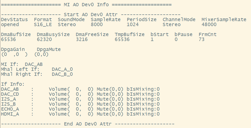
# cat proc/mi_modules/mi_ao/mi_ao0
-
Debug info analysis
Record the current AO usage status and device attributes, and can dynamically obtain information, which is convenient for debugging and testing.
-
Parameter Description
Parameter Description AO Device Attr DevStatus AO device status
uninit: uninit
opened: open sucessfullyFormat Audio format (Bit width and size end, etc)
Currently only support S16_LE (16bit, small end mode)SoundMode Sound mode: mono / stereo SampleRate Sample rate
8k/11.025k/12k/16k/22.05k/24k/32k/44.1k/48kPeriodSize AO starting condition (sample points) ChannelMode AO channel mode
Stereo
DoubleMono: Currently only support mono output by the left and right channel
DoubleLeft: Output two left channels
DoubleRight:Output two right channels
Exchange: Left and right channel exchange
OnlyLeft: Currently only support mono output by the left channel
Only Right: Currently only support mono output by the right channelMixerSampleRate Output sample rate after mixing.
8k/16k/32k/48k (Invalid currently)DmaBufSize DMA buffer size DmaBusySize DMA buffer busy size DmaFreeSize DMA buffer free size TmpBufSize Temporal buffer size bStart AO start DMA or not bPause AO pause DMA or not FrmCnt Write data frame count DpgaGain Digital gain: left channel gain, right channel gain DpgaMute DPGA mute: left channel mute, right channel mute MI If MI bind all interface information, that is, all interface information bound to the application layer Mhal Left If MHAL RDMA_L bind all interface information Mhal Right If MHAL RDMA_R bind all interface information If Info Interface volume, mute and other information
Volume (left channel gain, right channel gain)
Mute (left channel mute, right channel mute)AO I2S Status I2sMode I2S Tx work mode (Only valid when interface is I2S Tx)
i2s-master
i2s-slave
tdm-master
tdm-slaveI2sMclk I2S Tx Mclk frequency (Only valid when interface is I2S Tx)
disable: not use Mclk
Other values are the current Mclk frequencyI2sFmt I2S Tx data format (Only valid when interface is I2S Tx)
I2S-MSB: I2S format
LEFT-MSB: I2S left-justified formatbI2sSync Whether I2S RX and TX share clock (Only valid when interface is I2S Tx)
1: 4 wire mode,RX and TX share clock
0: 6 wire mode,RX and TX have independent clocksTdmSlots I2S Tx TDM slot number (Tx is TDM mode when interface is I2S) I2sBitWidth I2S TX bit width (Only valid when interface is I2S Tx and the chip supports TDM mode)
5.2. echo
| Features | Dynamically enable/disable AO device DPGA mute mode |
|---|---|
| Command | echo set_dpga_mute [LeftMute] [RightMute] [Fading] > proc/mi_modules/mi_ao/mi_ao[ID] |
| Parameter Description | [ON/on/1, OFF/off/0] Enable/Disable mute [Fading] Set the fading speed [ID] Device ID |
| Example | echo set_dpga_mute 1 0 0 > proc/mi_modules/mi_ao/mi_ao[ID] |
| Features | Dynamically enable/disable AO device interface mute mode |
|---|---|
| Command | echo set_inf_mute [If] [LeftMute] [RightMute] > proc/mi_modules/mi_ao/mi_ao[ID] |
| Parameter Description | [If]Interface to be set [ON/on/1, OFF/off/0] Enable/Disable mute [ID] Device ID |
| Example | echo set_inf_mute 1 1 0 > proc/mi_modules/mi_ao/mi_ao[ID] |
| Note | The tiny version does not support this cmd |
| Features | Dynamically set AO DPGA volume |
|---|---|
| Command | echo set_dpga_volume [LeftVolume] [RightVolume] [Fading] > proc/mi_modules/mi_ao/mi_ao[ID] |
| Parameter Description | [LeftVolume] [RightVolume] Left channel volume, right channel volume [Fading]Set the fading speed of volume |
| Example | echo set_dpga_volume -10 -10 0 > proc/mi_modules/mi_ao/mi_ao0 |
| Features | Dynamically set AO Interface volume |
|---|---|
| Command | echo set_inf_volume [If] [LeftVolume] [RightVolume] > proc/mi_modules/mi_ao/mi_ao[ID] |
| Parameter Description | [If]Interface to be set [LeftVolume] [RightVolume] Left channel volume, right channel volume |
| Example | Not support at present |
| Features | Dynamically enable/disable the dump data function of AO device |
|---|---|
| Command | echo dump_data [Path] [ON/on/1, OFF/off/0] > proc/mi_modules/mi_ao/mi_ao[ID] |
| Parameter Description | [Path] Path to dump data [ON/on/1, OFF/off/0] Enable/Disable the dump data function |
| Example | echo dump /mnt 1 > proc/mi_modules/mi_ao/mi_ao0 |
| Function | Dynamically enable/disable Singen of AO device |
|---|---|
| Command | echo singen [SinGen Index] [Enable] > proc/mi_modules/mi_ao/mi_ao[ID] |
| Parameter Description | [SinGen Index] Singen ID [Enable] Enable/Disable Singen |
| Example | echo singen 0 1 > proc/mi_modules/mi_ao/mi_ao0 |
| Note | The tiny version does not support this cmd |
| Function | Dynamically set channel mode of AO device |
|---|---|
| Command | echo set_chn_mode [channelMode] > proc/mi_modules/mi_ao/mi_ao[ID] |
| Parameter Description | [channelMode] channel mode of AO device |
| Example | echo set_chn_mode 0 > proc/mi_modules/mi_ao/mi_ao0 |