MI RGN API
REVISION HISTORY
| Revision No. | Description |
Date |
|---|---|---|
| 3.0 | 12/04/2020 | |
| 08/25/2021 | ||
| 02/16/2022 | ||
| 03/21/2022 |
1. OVERVIEW
1.1. Module Description
The region module is a part of an internal stream processing in ‘SCL’ modules. It is supported by hardware module named GOP (graphic output path), it is a set of software interface abstracted by GOP characteristics. OSD (on screen display) or cover attaches to each channel in the way of using time sharing multiplexing.
The region module mainly provides the control and management functions of region resources. It includes the creation, destruction, acquisition and the setting of region attributes, acquisition and the setting of channel display attributes of the region, etc.
There are two kind of region attributions, one is called ‘cover’, which is order to cover the video by a designated color. The hardware driver of ‘cover’ only need to get the cover’s position, size and the color, so that it will not get a display buffer.
The other region attribution is ‘osd’, also called ‘overlay’, It is same to 'cover', it can be attached to the display video area, but it is worked by display buffer, this kind of region can do a drew operation in point to point way, and the color format of ‘osd’ can support argb and bitmap. User can choose the color format according to the practical application scenarios.
Currently osd format supports ‘argb8888’, ‘argb1555’, ‘argb4444’, ‘rgb565’, ‘i2’, ‘i4’, ‘i8’. The format supporting conditions of each chip will be different. The following will be explained in detail. YUV format is not supported. I2, I4 and I8 are in bitmap format, and the memory data of a pixel is used as an index. Through the index, the color data in the color palette can be found, which the pixel displays is.
No matter ‘cover’ or ‘osd’, the display contents blending to the output of ‘scl’ module. Through experiments, when region display has been set, dump the output of ‘scl’ module into a file, and you can see the content of region through the tool.
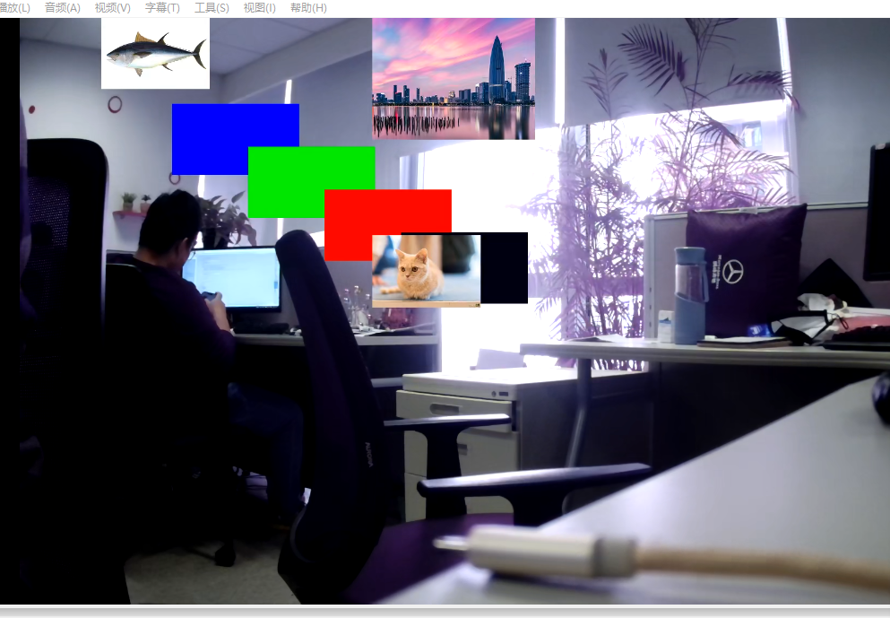
‘OSD’ can display a picture, ‘cover’ can only set different color, ‘Osd’ always display above ‘cover’ when they are attached the same path. This is a picture showed four ‘cover’ and three 'osd' attached to the same path.
1.2. Flow Chart

1.3. Keyword
I2:
4 colors bitmap, 2 bits refer to an index, so that there are 4 colors. It can find the color by the index in palette.
I4:
16 colors bitmap, 4 bits refer to an index and find the color by the index in palette.
I8:
256 colors bitmap, 8 bits refer to an index and find the color by the index in palette.
Palette:
The palette of bitmap, one color is represented by four 8bit variables: alpha, red, green and blue, there are totally 256 colors in palette with index range from 0 to 255.
OSD:
Abbreviation of on-screen display, It is used to display some text, pictures, UI menus and other contents.
GOP:
Abbreviation of graphic output path, it is a graphic layer above video.
1.4. RGN Memory Usage Description
In order to ensure that the OSD can be output to the video stably, RGN allocates one or more buffers to each OSD according to the hardware/user usage to prevent writing to the buffer being used for hardware display, causing OSD flickering or tearing.
The following will increase the memory usage of RGN:
- The update speed of the upper layer OSD(call MI_RGN_SetBitMap/MI_RGN_GetCanvasInfo/MI_RGN_UpdateCanvas) is accelerated;
- The number of channels superimposed on an OSD has increased;
- he number of OSDs superimposed on a channel at the same time exceeds the maximum hardware layer for the maximum number of hardware layers supported by each chip).
The following table lists the buffer usage in common scenarios:
| Scenario Description | OSD | OSD refresh rate t/each time |
Channel | buffer |
|---|---|---|---|---|
| 1 OSD attached to 1 channel, only attached once without refreshing | 1 | NA | 1 | 1 |
| 1 OSD attached to 1 channel, slow refresh | 1 | 1s | 1 | 2 |
| 1 OSD attached to 1 channel, fast refresh | 1 | 30ms | 1 | 3 |
| 1 OSD attached n channels, only attached once without refreshing | 1 | NA | n | 1 |
| 1 OSD attached n channels, slow refresh | 1 | 1s | n | 2 |
| 1 OSD attached n channels, fast refresh | 1 | 30ms | n | [3, 2n+1] |
| m OSDs attached to 1 channel, only attached once without refreshing | m <= L | NA | 1 | m |
| m OSDs attached to 1 channel, slow refresh | m <= L | 1s | 1 | 2m |
| m OSDs attached to 1 channel, fast refresh | m <= L | 30ms | 1 | 3m |
| m OSDs attached to n channels, only attached once without refreshing | m <= L | NA | n | m |
| m OSDs attached to n channels, slow refresh | m <= L | 1s | n | 2m |
| m OSDs attached to n channels, fast refresh | m <= L | 30ms | n | [3m, m(2n+1)] |
| m OSDs attached to n channels, only attached once without refreshing | m > L | NA | n | L + n(m - L) |
| m OSDs attached to n channels, slow refresh | m > L | 1s | n | 2L + 2n(m - L) |
| m OSDs attached to n channels, fast refresh | m > L | 30ms | n | [3L, L(2n+1)] + 3n(m–L) |
Note:
- L represents the maximum number of hardware layers;
- For example, [3, 2n+1] represents a closed interval, and the number of buffers is a certain value in this interval (affected by system scheduling, it usually does not reach the maximum value).
2. API LIST
| API | Function |
|---|---|
| MI_RGN_Init | Initialization |
| MI_RGN_DeInit | De-initialization |
| MI_RGN_Create | Create region |
| MI_RGN_Destroy | Destroy region |
| MI_RGN_GetAttr | Get region attributes |
| MI_RGN_SetBitMap | Set bitmap region |
| MI_RGN_AttachToChn | Attach region to channel |
| MI_RGN_DetachFromChn | Detach region from channel |
| MI_RGN_SetDisplayAttr | Set display attributes of region |
| MI_RGN_GetDisplayAttr | Get display attributes of region |
| MI_RGN_GetCanvasInfo | Get canvas information of region |
| MI_RGN_UpdateCanvas | Update canvas information of region |
| MI_RGN_InitDev | Initialize RGN device |
| MI_RGN_DeInitDev | De-initialize RGN device |
2.1. MI_RGN_Init
Function
Initialization.
Syntax
MI_S32 MI_RGN_Init(MI_U16 u16SocId, MI_RGN_PaletteTable_t *pstPaletteTable);
Parameters
| Parameter | Description | Input / Output |
|---|---|---|
| s32SocId | Chip ID for multiple chips | Input |
| pstPaletteTable | Pointer to the palette table | Input |
Return Value
- MI_RGN_OK: Successful
- MI_ERR_RGN_BUSY: Failed
Requirement
- Header file: mi_sys.h, mi_rgn.h.
- Library file
Note
The palette table can only be done once during initialization and cannot be set again.
It is not used for RGB color format.
The index of ‘0’ in palette array is used for colorkey, which will not display anything.
MI_RGN_Init needs to be done before Init of any other modules that use RGN (such as SCL).
Example
MI_S32 s32Result = 0;
MI_RGN_PaletteTable_t stPaletteTable;
memset(&stPaletteTable, 0, sizeof(MI_RGN_PaletteTable_t));
stPaletteTable.astElement[1].u8Alpha = 255;
stPaletteTable.astElement[1].u8Red = 255;
stPaletteTable.astElement[1].u8Green = 0;
stPaletteTable.astElement[1].u8Blue = 0;
stPaletteTable.astElement[2].u8Alpha = 255;
stPaletteTable.astElement[2].u8Red = 0;
stPaletteTable.astElement[2].u8Green = 255;
stPaletteTable.astElement[2].u8Blue = 0;
stPaletteTable.astElement[3].u8Alpha = 255;
stPaletteTable.astElement[3].u8Red = 0;
stPaletteTable.astElement[3].u8Green = 0;
stPaletteTable.astElement[3].u8Blue = 255;
s32Result = MI_RGN_Init(0, &stPaletteTable);
s32Result = MI_RGN_DeInit(0);
Related APIs
2.2. MI_RGN_DeInit
Function
De-initialization
Syntax
MI_S32 MI_RGN_DeInit(MI_U16 u16SocId);
Return Value
- MI_RGN_OK: Successful
- MI_ERR_RGN_BUSY: Failed
Requirement
- Header file: mi_sys.h, mi_rgn.h.
- Library file
Note
MI_RGN_Deinit needs to be done after Deinit of any other modules that use RGN (such as SCL).
Example
Refer to MI_RGN_Init
Related APIs
2.3. MI_RGN_Create
Function
Create region
Syntax
MI_S32 MI_RGN_Create(MI_U16 u16SocId, MI_RGN_HANDLE hHandle, MI_RGN_Attr_t *pstRegion);
Parameters
| Parameter | Description | Input / Output |
|---|---|---|
| s32SocId | Chip ID for multiple chips | Input |
| hHandle | Control code of region. Must be an unused hHandle Range: [0, MI_RGN_MAX_HANDLE). |
Input |
| pstRegion | Pointer to the attribute of region | Input |
Return Value
- MI_RGN_OK: Successful
- Not MI_RGN_OK: Failed. Please refer to Return Value
Requirement
- Header file: mi_sys.h, mi_rgn.h.
- Library file
Note
- This handle is specified by the user and has the same meaning as the ID.
- Repeated creation is not supported.
- The attribute of region must be legal. Refer to MI_RGN_Attr_t
- The pointer to attribute of region cannot be null.
- When creating a Cover, it only needs to assign the region type. Other attributes, such as location, hierarchy, etc., are assigned when the MI_RGN_AttachToChn interface is called.
- When creating a region, this only checks the basic parameters such as minimum width and height, maximum width and height. When this region is attached to the channel, more targeted parameters can be checked based on constraints of the supported type of channel module. Such as supported pixel formats, etc.
Example
MI_S32 s32Result = 0;
MI_RGN_HANDLE hHandle = 0;
MI_RGN_Attr_t stRegion;
stRegion.eType = E_MI_RGN_TYPE_OSD;
stRegion.stOsdInitParam.ePixelFmt = E_MI_RGN_PIXEL_FORMAT_RGB1555;
stRegion.stOsdInitParam.stSize.u32Width = 40;
stRegion.stOsdInitParam.stSize.u32Height = 40;

s32Result = MI_RGN_Create(0, hHandle, &stRegion);
if (s32Result != MI_RGN_OK)
{
    return s32Result;
}

s32Result = MI_RGN_GetAttr(0, hHandle, &stRegion);
if (s32Result != MI_RGN_OK)
{
    return s32Result;
}

s32Result = MI_RGN_Destroy(0, hHandle);
if (s32Result != MI_RGN_OK)
{
    return s32Result;
}
Related APIs
2.4. MI_RGN_Destroy
Function
Destroy region
Syntax
MI_S32 MI_REG_Destroy (MI_U16 u16SocId, MI_RGN_HANDLE hHandle);
Parameters
| Parameter | Description | Input / Output |
|---|---|---|
| s32SocId | Chip ID for multiple chips | Input |
| hHandle | Control code of region. Range: [0, MI_RGN_MAX_HANDLE). |
Input |
Return Value
- MI_RGN_OK: Successful
- Not MI_RGN_OK: Failed. Please refer to Return Value
Requirement
- Header file: mi_sys.h, mi_rgn.h.
- Library file:
Note
Region must have been created.
Example
Refer to MI_RGN_Create
Related APIs
2.5. MI_RGN_GetAttr
Function
Get the attribute of region.
Syntax
MI_S32 MI_RGN_GetAttr(MI_U16 u16SocId, MI_RGN_HANDLE hHandle, MI_RGN_Attr_t *pstRegion);
Parameters
| Parameter | Description | Input / Output |
|---|---|---|
| s32SocId | Chip ID for multiple chips | Input |
| hHandle | Control code of region. Range: [0, MI_RGN_MAX_HANDLE). |
Input |
| pstRegion | Pointer to the attribute of region. | Output |
Return Value
- MI_RGN_OK: Successful
- Not MI_RGN_OK: Failed. Please refer to Return Value
Requirement
- Header file: mi_sys.h, mi_rgn.h.
- Library file:
Note
- Region must have been created.
- The pointer to the attribute of region cannot be null.
Example
Refer to MI_RGN_Create.
2.6. MI_RGN_SetBitMap
Function
Set the region bitmap, that is, fill the region with bitmap.
Syntax
MI_S32 MI_RGN_SetBitMap(MI_U16 u16SocId, MI_RGN_HANDLE hHandle, MI_RGN_Bitmap_t *pstBitmap);
Parameters
| Parameter | Description | Input / Output |
|---|---|---|
| s32SocId | Chip ID for multiple chips | Input |
| hHandle | Control code of region. Range: [0, MI_RGN_MAX_HANDLE). |
Input |
| pstBitmap | The pointer to the attribute of bitmap | Input |
Return Value
- MI_RGN_OK: Successful
- Not MI_RGN_OK: Failed. Please refer to Return Value
Requirement
- Header file: mi_sys.h, mi_rgn.h.
- Library file:
Note
- Region must have been created.
- The size of the supported bitmap is inconsistent with the size of the region.
- The bitmap is loaded from (0,0) of the region. When the bitmap is larger than the region, the image will be automatically cropped into region.
- The pixel format of the bitmap must be the same as the pixel format of the region.
- The pointer to the attribute of bitmap cannot be null.
- Support multiple calls.
- This interface is only valid for overlay.
- After calling MI_RGN_GetCanvasInfo, calling this interface is invalid unless MI_RGN_UpdateCanvas is in effect.
Example
MI_S32 s32Result = 0;
MI_HANDLE hHandle = 0;
MI_RGN_Bitmap_t stBitmap;
MI_U32 u32FileSize = 200 * 200 * 2;
MI_U8 *pu8FileBuffer = NULL;
FILE *pFile = fopen("200X200.argb1555", "rb");
if (pFile == NULL)
{
    printf("open file failed \n");
    return -1;
}
pu8FileBuffer = (MI_U8*)malloc(u32FileSize);
if (pu8FileBuffer == NULL)
{
    printf("malloc failed fileSize=%d\n", u32FileSize);
    fclose(pFile);
    return -1;
}
memset(pu8FileBuffer, 0, u32FileSize);
fread(pu8FileBuffer, 1,  u32FileSize, pFile);
fclose(pFile);
stBitmap.stSize.u32Width = 200;
stBitmap.stSize.u32Height = 200;
stBitmap.ePixelFormat = E_MI_RGN_PIXEL_FORMAT_RGB1555;
stBitmap.pData = pu8FileBuffer;
free(pu8FileBuffer);
s32Result = MI_RGN_SetBitMap(0, hHandle, &stBitmap);
2.7. MI_RGN_AttachToChn
Function
Attach region to channel
Syntax
MI_S32 MI_RGN_AttachToChn(MI_U16 u16SocId, MI_RGN_HANDLE hHandle,
                            MI_RGN_ChnPort_t* pstChnPort,
                            MI_RGN_ChnPortParam_t *pstChnAttr);
Parameters
| Parameter | Description | Input / Output |
|---|---|---|
| s32SocId | Chip ID for multiple chips | Input |
| hHandle | Control code of region. Range: [0, MI_RGN_MAX_HANDLE). |
Input |
| pstChnPort | Pointer to channel port When region type is Cover and the output port is VPE, only port 0 and port 3 are valid. | Input |
| pstChnAttr | Pointer to the attribute of channel port. | Input |
Return Value
- MI_RGN_OK: Successful
- Not MI_RGN_OK: Failed. Please refer to Return Value
Requirement
- Header file: mi_sys.h, mi_rgn.h.
- Library file:
Note
- Region must have been created.
- Pointer to channel port cannot be null.
- Pointer to the attribute of channel port cannot be null.
- If two or more OSD regions are attached to the same channel, the format of these OSD regions must be the same.
- Not all channels have the ability to overlay regions. The table below lists the chip differences.
- ‘COVER’ can be worked by hardware layer. ‘OSD’ can be worked by software layer, which is implemented by software jigsaw.
- The channel id does not have any limitation about ‘OSD’ and ‘COVER’ attached on the channel.
- The OSD and COVER is not supported when SCL used rotate function.
- If the OSD attached on the channel is less than or equal to the number of hardware layers, all the hardware layers will be used, otherwise, the software jigsaw will be used.
-
The path in the table as below represent the SOC chip whether has GOP hardware module, which do not indicate the device id/ channel id/ port id. The user should find the actual path setting based on the actual situation of each module, and set driver by filling ‘MI_RGN_ChnPort_t* pstChnPort’.
- SCL corresponds to MI_SCL module, it usually bind hardware of SCL and software of device id / output port id when initializing. For more information, please refer to MI SCL API document.
- DISP corresponds to MI_DISP module. The DISPx in the table is bound to the device id of the MI_DISP module, and only the device id can be set. Channel id and Port id need to be filled with 0.
- JPE and VENC correspond to different devices of the MI_VENC module (Please refer to MI VENC API for details). The channel id is filled in according to the actual situation, and the port id corresponds to the input port id of MI_VENC.
Table 2-1: Chip information of Tiramisu
| Path | Hardware layer count of OSD | Max layer count of OSD | Cover Layer count | ARGB1555 | ARGB4444 | I2 | I4 | I8 | RGB565 | ARGB8888 |
|---|---|---|---|---|---|---|---|---|---|---|
| SCL0 | 8 | 128 | 4 | Y | Y | Y | Y | Y | NA | NA |
| SCL1 | 8 | 128 | 4 | Y | Y | Y | Y | Y | NA | NA |
| SCL2 | 8 | 128 | 4 | Y | Y | Y | Y | Y | NA | NA |
| SCL3 | 8 | 128 | 4 | Y | Y | Y | Y | Y | NA | NA |
| SCL4 | 8 | 128 | 4 | Y | Y | Y | Y | Y | NA | NA |
| SCL5 | 8 | 128 | 4 | Y | Y | Y | Y | Y | NA | NA |
The number of GOP hardware available in this series of chips is 6, and the OSD output ports are SCL0, SCL1, SCL2, SCL3, SCL4, SCL5 a total of 6.
Table 2-2: Chip information of Muffin
| Path | Hardware layer count of OSD | Max layer count of OSD | Cover Layer count | ARGB1555 | ARGB4444 | I2 | I4 | I8 | RGB565 | ARGB8888 |
|---|---|---|---|---|---|---|---|---|---|---|
| SCL0 | 8 | 128 | 4 | Y | Y | Y | Y | Y | NA | NA |
| SCL1 | 8 | 128 | 4 | Y | Y | Y | Y | Y | NA | NA |
| SCL2 | 8 | 128 | 4 | Y | Y | Y | Y | Y | NA | NA |
| SCL3 | 8 | 128 | 4 | Y | Y | Y | Y | Y | NA | NA |
| SCL4 | 8 | 128 | 4 | Y | Y | Y | Y | Y | NA | NA |
| SCL5 | 8 | 128 | 4 | Y | Y | Y | Y | Y | NA | NA |
| SCL6 | 8 | 128 | 4 | Y | Y | Y | Y | Y | NA | NA |
| SCL7 | 8 | 128 | 4 | Y | Y | Y | Y | Y | NA | NA |
| SCL8 | 8 | 128 | 4 | Y | Y | Y | Y | Y | NA | NA |
| VENC0 | 8 | 128 | NA | Y | Y | Y | Y | Y | NA | NA |
| VENC1 | 8 | 128 | NA | Y | Y | Y | Y | Y | NA | NA |
| JPE0 | 8 | 128 | NA | Y | Y | Y | Y | Y | NA | NA |
| JPE1 | 8 | 128 | NA | Y | Y | Y | Y | Y | NA | NA |
| DISP0 | 1 | 128 | NA | Y | Y | Y | Y | Y | NA | NA |
| DISP1 | 1 | 128 | NA | Y | Y | Y | Y | Y | NA | NA |
| DISP2 | 1 | 128 | NA | Y | Y | Y | Y | Y | NA | NA |
- The number of GOP hardware available on SCL in this series is 2, and the OSD output ports are SCL 0/ 1/ 2/ 3/ 4/ 5/ 6/ 7/ 8. SCL 0/ 1/ 2/ 3 share the same GOP hardware. SCL 4/ 5/ 6/ 7/ 8 share the same GOP hardware. When multiple SCL share the same GOP, only one SCL can be attached OSD at the same time.
- For VENC/JPE/DISP, each device has its own GOP.
- Constant alpha cannot be used when the number of VENC/JPE OSD exceeds 8.
Table 2-3: Chip information of Mochi
| Path | Hardware layer count of OSD | Max layer count of OSD | Cover Layer count | ARGB1555 | ARGB4444 | I2 | I4 | I8 | RGB565 | ARGB8888 |
|---|---|---|---|---|---|---|---|---|---|---|
| SCL0 | 8 | 128 | 4 | Y | Y | Y | Y | Y | NA | NA |
| SCL1 | 8 | 128 | 4 | Y | Y | Y | Y | Y | NA | NA |
| SCL2 | 8 | 128 | 4 | Y | Y | Y | Y | Y | NA | NA |
| SCL3 | 8 | 128 | 4 | Y | Y | Y | Y | Y | NA | NA |
| SCL4 | 8 | 128 | 4 | Y | Y | Y | Y | Y | NA | NA |
| SCL5 | 8 | 128 | 4 | Y | Y | Y | Y | Y | NA | NA |
| SCL6 | 8 | 128 | 4 | Y | Y | Y | Y | Y | NA | NA |
| VENC0 | 8 | 128 | NA | Y | Y | Y | Y | Y | NA | NA |
| JPE0 | 8 | 128 | NA | Y | Y | Y | Y | Y | NA | NA |
| JPE1 | 8 | 128 | NA | Y | Y | Y | Y | Y | NA | NA |
| DISP0 | 1 | 128 | NA | Y | Y | Y | Y | Y | NA | NA |
| DISP1 | 1 | 128 | NA | Y | Y | Y | Y | Y | NA | NA |
- The number of GOP hardware available on SCL in this series is 1, and the OSD output ports are SCL 0/ 1/ 2/ 3/ 4/ 5/ 6. All of them share the same GOP hardware. When multiple SCL share the same GOP, only one SCL can be attached OSD at the same time.
- For VENC/JPE/DISP, each device has its own GOP.
- Constant alpha cannot be used when the number of VENC/JPE OSD exceeds 8.
Table 2-4: Chip information of Maruko
| Path | Hardware layer count of OSD | Max layer count of OSD | Cover Layer count | ARGB1555 | ARGB4444 | I2 | I4 | I8 | RGB565 | ARGB8888 |
|---|---|---|---|---|---|---|---|---|---|---|
| SCL0 | 8 | 128 | 4 | Y | Y | Y | Y | Y | NA | NA |
| SCL1 | 8 | 128 | 4 | Y | Y | Y | Y | Y | NA | NA |
| SCL2 | 8 | 128 | 4 | Y | Y | Y | Y | Y | NA | NA |
| SCL3 | 8 | 128 | 4 | Y | Y | Y | Y | Y | NA | NA |
| VENC0 | 8 | 128 | NA | Y | Y | Y | Y | Y | NA | NA |
| JPE0 | 8 | 128 | NA | Y | Y | Y | Y | Y | NA | NA |
| DISP0 | 8 | 128 | NA | Y | Y | Y | Y | Y | NA | NA |
- SCL and DISP in this series of chips share the same GOP hardware, and the OSD output ports are SCL 0/ 1/ 2/ 3 and DISP 0. When multiple modules share the same GOP, only one module can be attached OSD at the same time.
- For VENC/JPE, each device has its own GOP.
Example
MI_S32 s32Result = 0;
MI_RGN_HANDLE hHandle = 0;
MI_RGN_ChnPort_t stChnPort;
MI_RGN_ChnPortParam_t stChnAttr;

memset(stChnPort, 0, sizeof(MI_RGN_ChnPort_t));
memset(stChnAttr, 0, sizeof(MI_RGN_ChnPortParam_t));
stChnPort.eModId = E_MI_MODULE_ID_SCL;
stChnPort.s32DevId = 0;
stChnPort.s32ChnId = 0;
stChnPort.s32PortId = 0;
stChnAttr.bShow = TRUE;
stChnAttr.stPoint.u32X = 0;
stChnAttr.stPoint.u32Y = 0;
stChnAttr.unPara. stCoverChnPort.u32Layer = 0;
stChnAttr.unPara. stCoverChnPort.stSize.u32Width = 200;
stChnAttr.unPara. stCoverChnPort.stSize.u32Height = 200;
stChnAttr.unPara. stCoverChnPort.u32Color = 0;

s32Result = MI_RGN_AttachToChn(0, hHandle, &stChnPort, &stChnAttr);
if (s32Result != MI_RGN_OK)
{
    return s32Result;
}

s32Result = MI_RGN_DetachFromChn(0, hHandle, &stChnPort);
if (s32Result != MI_RGN_OK)
{
   return s32Result;
}
Related APIs
2.8. MI_RGN_DetachFromChn
Function
Detach region from channel
Syntax
MI_S32 MI_RGN_DetachFromChn(MI_U16 u16SocId, MI_RGN_HANDLE hHandle, MI_RGN_ChnPort_t *pstChnPort);
Parameters
| Parameter | Description | Input / Output |
|---|---|---|
| s32SocId | Chip ID for multiple chips | Input |
| hHandle | Control code of region. Range: [0, MI_RGN_MAX_HANDLE). |
Input |
| pstChnPort | The pointer to channel port | Input |
Return Value
- MI_RGN_OK: Successful
- Not MI_RGN_OK: Failed. Please refer to Return Value
Requirement
- Header file: mi_sys.h, mi_rgn.h.
- Library file:
Note
- Region must have been created.
- The pointer to channel port cannot be null.
- Before the overlaid channel or modules, such as VENC or SCL, is destroyed, it needs to call this interface to detach from region channel or module.
Example
Refer to MI_RGN_AttachToChn.
Related APIs
2.9. MI_RGN_SetDisplayAttr
Function
Set the display attribute of region.
Syntax
MI_S32 MI_RGN_SetDisplayAttr(MI_U16 u16SocId, MI_RGN_HANDLE hHandle,
                                MI_RGN_ChnPort_t *pstChnPort,
                                MI_RGN_ChnPortParam_t *pstChnPortAttr);
Parameters
| Parameter | Description | Input / Output |
|---|---|---|
| s32SocId | Chip ID for multiple chips | Input |
| hHandle | Control code of region. Range: [0, MI_RGN_MAX_HANDLE). |
Input |
| pstChnPort | The pointer to channel port | Input |
| pstChnPortAttr | The pointer to the parameter of channel port | Input |
Return Value
- MI_RGN_OK: Successful
- Not MI_RGN_OK: Failed. Please refer to Return Value
Requirement
- Header file: mi_sys.h, mi_rgn.h.
- Library file:
Note
- Region must have been created.
- It is recommended to obtain the attributes first and then set them.
- The pointer to channel port cannot be null.
- The pointer to the parameter of channel port cannot be null.
- The region must overlay with channel first.
- Static properties cannot be modified, dynamic properties can be modified. Refer to MI_RGN_ChnPortParam_t
Example
MI_S32 s32Result = 0;
MI_RGN_HANDLE hHandle = 0;
MI_RGN_ChnPort_t stChnPort;
MI_RGN_ChnPortParam_t stChnAttr;

stChnPort.eModId = E_MI_MODULE_ID_SCL;
stChnPort.s32DevId = 0;
stChnPort.s32ChnId = 0;
stChnPort.s32OutputPortId = 0;
s32Result = MI_RGN_GetDisplayAttr(0, hHandle, &stChnPort, &stChnAttr);
if (s32Result != MI_RGN_OK)
{
    return s32Result;
}


stChnAttr.bShow = TRUE;
stChnAttr.stPoint.u32X = 0;
stChnAttr.stPoint.u32Y = 0;
stChnAttr.stCoverPara.u32Layer = 0;
stChnAttr.stCoverPara.stSize.u32Width = 200;
stChnAttr.stCoverPara.stSize.u32Height = 200;
stChnAttr.stCoverPara.u32Color = 0;

s32Result = MI_RGN_SetDisplayAttr(0, hHandle, &stChnPort, &stChnAttr);
if (s32Result != MI_RGN_OK)
{
    return s32Result;
}
Related APIs
2.10. MI_RGN_GetDisplayAttr
Function
Get the display attribute of region.
Syntax
MI_S32 MI_RGN_GetDisplayAttr(MI_U16 u16SocId, MI_RGN_HANDLE hHandle,
                                MI_RGN_ChnPort_t *pstChnPort,
                                MI_RGN_ChnPortParam_t *pstChnPortAttr);
Parameters
| Parameter | Description | Input / Output |
|---|---|---|
| s32SocId | Chip ID for multiple chips | Input |
| hHandle | Control code of region. Range: [0, MI_RGN_MAX_HANDLE). |
Input |
| pstChnPort | The pointer to channel port | Input |
| pstChnPortAttr | The pointer to the parameter of channel port | Output |
Return Value
- MI_RGN_OK: Successful
- Not MI_RGN_OK: Failed. Please refer to Return Value
Requirement
- Header file: mi_sys.h, mi_rgn.h.
- Library file:
Note
- Region must have been created.
- The pointer to channel port cannot be null.
- The pointer to the parameter of channel port cannot be null.
Example
Refer to MI_RGN_SetDisplayAttr.
Related APIs
2.11. MI_RGN_GetCanvasInfo
Function
Get the canvas information of region.
Syntax
MI_S32 MI_RGN_GetCanvasInfo(MI_U16 u16SocId, MI_RGN_HANDLE hHandle, MI_RGN_CanvasInfo_t* pstCanvasInfo);
Parameters
| Parameter | Description | Input / Output |
|---|---|---|
| s32SocId | Chip ID for multiple chips | Input |
| hHandle | Control code of region. Range: [0, MI_RGN_MAX_HANDLE). |
Input |
| pstCanvasInfo | Pointer to the canvas information of region | Output |
Return Value
- MI_RGN_OK: Successful
- Not MI_RGN_OK: Failed. Please refer to Return Value
Requirement
- Header file: mi_sys.h, mi_rgn.h.
- Library file:
Note
-
Region must have been created.
-
This interface is similar to MI_RGN_SetBitMap and is mainly used for overlay types to import bitmap data. This interface is relative to MI_RGN_SetBitMap, users can update directly to display the internal data of canvas, which can save one memory copy and one memory’s allocation.
- This interface is used to obtain canvas information corresponding to a region. After getting the canvas address, the user can directly operate the canvas. For example: Fill bmp data directly into the canvas, then update the display canvas data by calling MI_RGN_UpdateCanvas.
- This interface is mutually exclusive with MI_RGN_SetBitMap. If this interface is already in use, calling MI_RGN_SetBitMap does not take effect until MI_RGN_UpdateCanvas is called.
Example
MI_RGN_HANDLE hHandle;
MI_RGN_Attr_t stRegion;
MI_RGN_PaletteTable_t stPaletteTable;
MI_RGN_CanvasInfo_t stCanvasInfo;

memset(&stPaletteTable, 0, sizeof(MI_RGN_PaletteTable_t));
stPaletteTable.astElement[0].u8Alpha = 0;
stPaletteTable.astElement[0].u8Red = 255;
stPaletteTable.astElement[0].u8Green = 255;
stPaletteTable.astElement[0].u8Blue = 255;
if (MI_RGN_OK != MI_RGN_Init(0, &stPaletteTable))
{
    printf("Init error!\n");
    return -1;
}
hHandle = 10;
stRegion.eType = E_MI_RGN_TYPE_OSD;
stRegion.stOsdInitParam.ePixelFmt = E_MI_RGN_PIXEL_FORMAT_ARGB1555;
stRegion.stOsdInitParam.stSize.u32Width = 100;
stRegion.stOsdInitParam.stSize.u32Height = 100;
if (MI_RGN_OK != MI_RGN_Create(0, hHandle, &stRegion))
{
    printf("Create handle error!\n");

    return -1;
}
FILE *pFile = fopen("100X100.argb1555", "rb");
if (pFile == NULL)
{
    printf("open file failed \n");
    MI_RGN_Destroy(0, hHandle);

    return -1;
}
if (MI_RGN_GetCanvas(0, hHandle, &stCanvasInfo) != MI_RGN_OK)
{
    return s32Result;
}

for (int i = 0; i < 100; i++)
{
    fread((MI_U8*)stCanvasInfo.virtAddr + i * stCanvasInfo.u32Stride, 1, 100 * 2, pFile);
}
fclose(pFile);
if (MI_RGN_UpdateCanvas(0, hHandle) != MI_RGN_OK)
{
    return s32Result;
}
Related APIs
2.12. MI_RGN_UpdateCanvas
Function
Update canvas. If the canvas is attached to the path, it will display on video, otherwise it will display after attach.
Syntax
MI_S32 MI_RGN_UpdateCanvas(MI_U16 u16SocId, MI_RGN_HANDLE hHandle);
Parameters
| Parameter | Description | Input / Output |
|---|---|---|
| s32SocId | Chip ID for multiple chips | Input |
| hHandle | Control code of region. Range: [0, MI_RGN_MAX_HANDLE). |
Input |
Return Value
- MI_RGN_OK: Successful
- Not MI_RGN_OK: Failed. Please refer to Return Value
Requirement
- Header file: mi_sys.h, mi_rgn.h.
- Library file:
Note
- Region must have been created.
- This interface is used with MI_REG_GetCanvasInfo. It is mainly used for canvas switching display after the canvas memory data is updated.
- This interface must be called by pair with MI_REG_GetCanvasInfo. It is used after user calls MI_REG_GetCanvasInfo to get the pointer of canvas and the draw operation has done. Without calling MI_REG_GetCanvasInfo first, this interface will return MI_ERR_RGN_NOT_PERM.
- If two or more handler have attached to the same path, and all this handlers use MI_REG_GetCanvasInfo and this interface to draw, draw operation can work normally on the same thead, If it work on different thread, it must use ‘mutex’ lock to protect, or it may cause ‘osd’ flicker or disappearance .
-
The detail note of multithreading’s ‘mutex’ lock usage is as below:
Suppose ‘handler0’ and ‘handler1’, which run on two threads, attach to the same path.
  handler0:
      T0_0 = getcanvas
      T0_1 = update
  handler1:
      T1_0 = getcanvas
      T1_1 = update
The wrong situation below is running in order of time, which is showing error log ‘‘Front buf state error!!!’’.
T0_0 -\> T1_0 -\> T0_1 -\> T1_1After using ‘mutex’, it will work fine:
lock-\> T0_0 -\> T0_1 -\> unlock -\> lock -\> T1_0 -\> T1_1 -\> unlock
Example
Refer to MI_RGN_GetCanvasInfo.
Related APIs
2.13. MI_RGN_InitDev
Function
Initialize RGN device
Syntax
MI_S32 MI_RGN_InitDev(MI_U16 u16SocId, MI_RGN_InitParam_t *pstInitParam);
Parameters
| Parameter | Description | Input / Output |
|---|---|---|
| s32SocId | Chip ID for multiple chips | Input |
| pstInitParam | Initialization Parameter | Input |
Return Value
- MI_RGN_OK: Successful
- Not MI_RGN_OK: Failed. Please refer to Return Value
Requirement
- Header file: mi_sys.h, mi_rgn.h.
- Library file
Note
Using this interface to replace the original MI_RGN_Init interface.
2.14. MI_RGN_DeInitDev
Function
De-initialize RGN device
Syntax
MI_S32 MI_RGN_DeInitDev(MI_U16 u16SocId);
Parameters
| Parameter | Description | Input / Output |
|---|---|---|
| s32SocId | Chip ID for multiple chips | Input |
Return Value
- MI_RGN_OK: Successful
- Not MI_RGN_OK: Failed. Please refer to Return Value
Requirement
- Header file: mi_sys.h, mi_rgn.h.
- Library file
Note
Using this interface to replace the original MI_RGN_DeInit interface.
3. RGN DATA TYPE
The data types of video pre-processing and their data structures are defined as follows:
| Data type | Definition |
|---|---|
| MI_RGN_MAX_HANDLE | The maximum number of control codes of region. |
| MI_RGN_MAX_PALETTE_TABLE_NUM | The maximum number of palette table |
| MI_RGN_HANDLE | The definition for the control code of region |
| MI_RGN_Type_e | The enumeration of region type |
| MI_RGN_PixelFormat_e | The enumeration of Pixel format |
| MI_RGN_AlphaMode_e | The way to display with alpha mode |
| MI_RGN_Size_t | The structure of the region size |
| MI_RGN_OsdAlphaAttr_t | The structure of the attribute of OSD ‘alpha’. |
| MI_RGN_OsdInitParam_t | The structure of the attribute of OSD region |
| MI_RGN_PaletteElement_t | The structure of Palette element |
| MI_RGN_PaletteTable_t | The structure of Palette table |
| MI_RGN_Attr_t | The structure of region attribute |
| MI_RGN_Bitmap_t | The attribute of bitmap attribute |
| MI_RGN_ChnPort_t | The structure of channel port |
| MI_RGN_Point_t | The structure of coordinates |
| MI_RGN_CoverChnPortParam_t | The structure of the covered channel port |
| MI_RGN_OsdChnPortParam_t | The structure of the OSD channel port |
| MI_RGN_OsdArgb1555Alpha_t | Foreground and background Alpha settings of Argb1555 format |
| MI_RGN_ChnPortParamUnion_u | The union of region channel port |
| MI_RGN_AlphaModePara_u | The union of osd alpha mode parameters |
| MI_RGN_ChnPortParam_t | The structure of the attribute of channel port |
| MI_RGN_CanvasInfo_t | The structure of canvas information |
| MI_RGN_InitParam_t | Define the initialized parameter of RGN device |
3.1. MI_RGN_MAX_HANDLE
Description
The definition for the maximum control code of region.
Definition
#define MI_RGN_MAX_HANDLE 1024
3.2. MI_RGN_MAX_PALETTE_TABLE_NUM
Description
The maximum number of palette table.
Definition
#define MI_RGN_MAX_PALETTE_TABLE_NUM 256
3.3. MI_RGN_HANDLE
Description
The definition for the control code of region
Definition
typedef MI_U32 MI_RGN_HANDLE;
Members
| Member | Description |
|---|---|
| MI_RGN_HANDLE | The control code of region. |
3.4. MI_RGN_Type_e
Description
The enumeration of region type
Definition
typedef enum
{
    E_MI_RGN_TYPE_OSD = 0,
    E_MI_RGN_TYPE_COVER,
    E_MI_RGN_TYPE_MAX
} MI_RGN_Type_e;
Members
| Member | Description |
|---|---|
| E_MI_ REG_OSD | Video overlaid region |
| E_MI_REG_COVER | Video covered region |
3.5. MI_RGN_PixelFormat_e
Description
The enumeration of Pixel format.
Definition
typedef enum
{
    E_MI_RGN_PIXEL_FORMAT_ARGB1555 = 0,
    E_MI_RGN_PIXEL_FORMAT_ARGB4444,
    E_MI_RGN_PIXEL_FORMAT_I2,
    E_MI_RGN_PIXEL_FORMAT_I4,
    E_MI_RGN_PIXEL_FORMAT_I8,
    E_MI_RGN_PIXEL_FORMAT_RGB565,
    E_MI_RGN_PIXEL_FORMAT_ARGB8888,
    E_MI_RGN_PIXEL_FORMAT_MAX
} MI_RGN_PixelFormat_e;
Members
| Member | Description |
|---|---|
| E_MI_RGN_PIXEL_FORMAT_ARGB1555 | ARGB1555 format |
| E_MI_RGN_PIXEL_FORMAT_ARGB4444 | ARGB4444 format |
| E_MI_RGN_PIXEL_FORMAT_RGBI2 | 2 bit representation. Can support 4 colors. Check color by the palette table. |
| E_MI_RGN_PIXEL_FORMAT_RGBI4 | 4 bit representation. Can support 16 colors. Check color by the palette table. |
| E_MI_RGN_PIXEL_FORMAT_I8 | 8 bit representation. Can support 256 colors. Check color by the palette table. |
| E_MI_RGN_PIXEL_FORMAT_RGB565 | RGB565 |
| E_MI_RGN_PIXEL_FORMAT_ARGB8888 | ARGB8888 format |
Note
The image format supported by each chip is different. The APIs list all image formats, but some formats may not be supported by the API. If users need chip support, please refer to region procfs.
Command: echo getcap > /proc/mi_modules/mi_rgn/mi_rgn0
Users cannot set the index 0 of the color palette. The index 0 of these formats is used as the color key by the underlying driver. That means this color is not recognized by hardware, so when all 0 data is covered on the channel, no color is displayed.
The value of the Color key can be viewed in the getcap of procfs. The value of color key is a 16bit integer. Its high 8 bits and low 8 bits are the same value. When using the color format of the Index type, memset 0 on the memory data can make the hardware not recognized. When using the RGB or ARGB format, no matter what arrangement is used, the memset (color key & 0xFF) value can be used for the memory data.
3.6. MI_RGN_AlphaMode_e
Description
The way to display with alpha mode.
Definition
typedef enum
{
    E_MI_RGN_PIXEL_ALPHA = 0,
    E_MI_RGN_CONSTANT_ALPHA,
} MI_RGN_AlphaMode_e;
Members
| Member | Description |
|---|---|
| E_MI_RGN_PIXEL_ALPHA | OSD display every pixel with alpha value, which can support by these color formats ‘argb1555/argb4444/arbg8888/i2/i4/i8’. Rgb565 without alpha value does not make sense. |
| E_MI_RGN_CONSTANT_ALPHA | The hardware ignores the alpha value (if exist) from the pixel format, In fact it use the specified alpha value to take the place of the original alpha value of each pixel. |
3.7. MI_RGN_Size_t
Description
The structure of the region size
Definition
typedef struct MI_RGN_Size_s
{
    MI_U32 u32Width;
    MI_U32 u32Height;
} MI_RGN_Size_t;
Members
| Member | Description |
|---|---|
| u32Width | Width |
| u32Height | Height |
3.8. MI_RGN_OsdAlphaAttr_t
Description
The structure of the attribute of OSD ‘alpha’.
Definition
typedef struct MI_RGN_OsdAlphaAttr_s
{
    MI_RGN_AlphaMode_e eAlphaMode;
    MI_RGN_AlphaModePara_u stAlphaPara;
}MI_RGN_OsdAlphaAttr_t;
Members
| Member | Description |
|---|---|
| eAlphaMode | The OSD alpha mode enum. |
| stAlphaPara | The parameters of alpha mode. |
3.9. MI_RGN_OsdInitParam_t
Description
The structure of the attribute of OSD region.
Definition
typedef struct MI_RGN_OsdInitParam_s
{
    MI_RGN_PixelFormat_e ePixelFmt;
    MI_RGN_Size_t stSize;
}MI_RGN_OsdInitParam_t;
Members
| Member | Description |
|---|---|
| ePixelFmt | Pixel format |
| stSize | The width and height of region Range: Width: It is related to output port resolution(8pixel alignment).TBD Height: It is related to output port resolution (2pixel alignment). |
Note
-
ePixelFmt, stSize are meaningful only after calling MI_RGN_AttachToChn.
-
ePixelFmt and stSize are static variables before calling MI_RGN_DetachFromChn
3.10. MI_RGN_PaletteElement_t
Description
The structure of the palette element of region
Definition
typedef struct MI_RGN_PaletteElement_s
{
    MI_U8 u8Alpha;
    MI_U8 u8Red;
    MI_U8 u8Green;
    MI_U8 u8Blue;
}MI_RGN_PaletteElement_t;
Members
| Member | Description |
|---|---|
| u8Alpha | Alpha |
| u8Red | Red |
| u8Green | Green |
| u8Blue | Blue |
3.11. MI_RGN_PaletteTable_t
Description
The structure of Palette table.
Definition
typedef struct MI_RGN_PaletteTable_s
{
    MI_RGN_PaletteElement_t astElement[MI_RGN_MAX_PALETTE_TABLE_NUM];
}MI_RGN_PaletteTable_t;
Members
| Member | Description |
|---|---|
| astElement | Color element |
3.12. MI_RGN_Attr_t
Description
The structure of region attribute.
Definition
typedef struct MI_RGN_Attr_s
{
    MI_RGN_Type_e eType;
    MI_RGN_OsdInitParam_t stOsdInitParam;
}MI_RGN_Attr_t;
Members
| Member | Description |
|---|---|
| eType | Region type |
| stOsdInitParam | Region attribute of OSD |
3.13. MI_RGN_Bitmap_t
Description
The attribute of bitmap attribute.
Definition
typedef struct MI_RGN_Bitmap_s
{
    MI_RGN_PixelFormat_e ePixelFormat;
    MI_RGN_Size_t stSize;
    void *pData;
} MI_RGN_Bitmap_t;
Members
| Member | Description |
|---|---|
| ePixelFormat | Pixel format |
| stSize | Bitmap width, height and stride |
| pData | The data of bitmap |
3.14. MI_RGN_ChnPort_t
Description
The structure of channel port
Definition
typedef struct MI_RGN_ChnPort_s
{
    MI_ModuleId_e  eModId;
    MI_S32 s32DevId;
    MI_S32 s32ChnId;
    MI_S32 s32PortId;
}MI_RGN_ChnPort_t;
Members
| Member | Description |
|---|---|
| eModId | Module ID |
| s32DevId | Device ID |
| s32ChnId | Channel ID |
| s32PortId | Output port ID |
3.15. MI_RGN_Point_t
Description
The structure of coordinates.
Definition
typedef struct MI_RGN_Point_s
{
    MI_U32 u32X;
    MI_U32 u32Y;
}MI_RGN_Point_t;
Members
| Member | Description |
|---|---|
| u32X | X-axis |
| u32Y | Y-axis |
3.16. MI_RGN_CoverChnPortParam_t
Description
The structure of the covered channel port
Definition
typedef struct MI_RGN_CoverChnPortParam_s
{
    MI_U32 u32Layer;
    MI_RGN_Size_t stSize;
    MI_U32 u32Color;
}MI_RGN_CoverChnPortParam_t;
Members
| Member | Description |
|---|---|
| u32Layer | Layer, low value at the bottom. |
| stSize | Width, height |
| u32Color | Color, VYU444 |
Note
-
The width and height of the cover are relative values based on the maximum value (8192).
For example, if the size of target channel is 1920x1080, to set the size of the cover to 960x540,the stSize of the cover should be set to (4096, 4096).
-
u32Color represents the display color of the Cover, where 23 ~ 16 bits represent the V component, 15 ~ 8 bits represent the Y component, and 7 ~ 0 represent the U component.
3.17. MI_RGN_OsdChnPortParam_t
Description
The structure of the OSD channel port
Definition
typedef struct MI_RGN_OsdChnPortParam_s
{
    MI_U32 u32Layer;
    MI_RGN_OsdAlphaAttr_t stOsdAlphaAttr;
}MI_RGN_OsdChnPortParam_t;
Members
| Member | Description |
|---|---|
| u32Layer | Layer, low value at the bottom. |
| stOsdAlphaAttr | Osd Alpha attribute. |
3.18. MI_RGN_OsdArgb1555Alpha_t
Description
Argb1555 only has one bit to describe the alpha, which divide two settings, the foreground alpha with alpha bit equal ‘1’ and background alpha with alpha bit equal ‘0’.
Definition
typedef struct MI_RGN_OsdArgb1555Alpha_s
{
    MI_U8 u8BgAlpha;
    MI_U8 u8FgAlpha;
}MI_RGN_OsdArgb1555Alpha_t;
Members
| Member | Description |
|---|---|
| u8BgAlpha | The alpha value to display in background when alpha bit is 0. Value range: 0~0xFF. |
| u8FgAlpha | The alpha value to display in foreground when alpha bit is 1. Value range: 0~0xFF. |
3.19. MI_RGN_ChnPortParamUnion_u
Description
The union of region channel port
Definition
typedef union
{
    MI_RGN_CoverChnPortParam_t stCoverChnPort;
    MI_RGN_OsdChnPortParam_t stOsdChnPort;
} MI_RGN_ChnPortParamUnion_u;
Members
| Member | Description |
|---|---|
| stCoverChnPort | The attribute of covered channel port |
| stOsdChnPort | The attribute of OSD region on channel port. |
3.20. MI_RGN_AlphaModePara_u
Description
The union of osd alpha mode parameters.
Definition
typedef union
{
    MI_RGN_OsdArgb1555Alpha_t stArgb1555Alpha;
    MI_U8 u8ConstantAlpha;
} MI_RGN_AlphaModePara_u;
Members
| Member | Description |
|---|---|
| stArgb1555Alpha | The setting of argb1555 format foreground and background alpha. |
| u8ConstantAlpha | The setting in constant alpha case, and value range is from 0 to 0xFF. |
3.21. MI_RGN_ChnPortParam_t
Description
The structure of the attribute of channel port.
Definition
typedef struct MI_RGN_ChnPortParam_s
{
    MI_BOOL bShow;
    MI_RGN_Point_t stPoint;
    MI_RGN_ChnPortParamUnion_u unPara;
} MI_RGN_ChnPortParam_t;
Members
| Member | Description |
|---|---|
| bShow | Whether the area is displayed. Range: MI_TRUE or MI_FALSE. Dynamic attribute. |
| stPoint | Starting point coordinate |
| unPara | The display attribute of channel port. |
3.22. MI_RGN_CanvasInfo_t
Description
The structure of canvas information
Definition
typedef struct MI_RGN_CanvasInfo_s
{
    MI_PHY phyAddr;
    MI_VIRT virtAddr;
    MI_RGN_Size_t stSize;
    MI_U32 u32Stride;
    MI_RGN_PixelFormat_e ePixelFmt;
} MI_RGN_CanvasInfo_t;
Members
| Member | Description |
|---|---|
| phyAddr | The physical address of canvas |
| virtAddr | The virtual address of canvas |
| stSize | The size of canvas |
| u32Stride | The stride of canvas |
| ePixelFmt | The pixel format of canvas |
3.23. MI_RGN_InitParam_t
Description
RGN device initialization parameter.
Definition
typedef struct MI_RGN_InitParam_s
{
    MI_RGN_PaletteTable_t *pstPaletteTable;
} MI_RGN_InitParam_t;
Members
| Member | Description |
|---|---|
| pstPaletteTable | Color element pointer |
Relevant data types and interface
4. RETURN VALUE
The return values of region module is shown in the following table.
| Error Code | Marco definition | Description |
|---|---|---|
| 0 | MI_RGN_OK | Success. |
| 0xA0030000 | MI_NOTICE_RGN_BUFFER_CHANGE | Buffer changed. This happens when the attribute is set and needs to be remapped again |
| 0xA0030001 | MI_ERR_RGN_INVALID_HANDLE | Invalid handle. |
| 0xA0030001 | MI_ERR_RGN_INVALID_DEVID | Invalid Device ID. |
| 0xA0030002 | MI_ERR_RGN_INVALID_CHNID | Invalid channel ID or the control code |
| 0xA0030003 | MI_ERR_RGN_ILLEGAL_PARAM | Illegal parameters. |
| 0xA0030004 | MI_ERR_RGN_EXIST | Repeat creating the existing devices, channels, or resources. |
| 0xA0030005 | MI_ERR_RGN_UNEXIST | Trying to use or destroy a device, channel, or resource that does not exist. |
| 0xA0030006 | MI_ERR_RGN_NULL_PTR | Null pointer |
| 0xA0030007 | MI_ERR_RGN_NOT_CONFIG | Not configured |
| 0xA0030008 | MI_ERR_RGN_NOT_SUPPORT | Not supported |
| 0xA0030009 | MI_ERR_RGN_NOT_PERM | This operation is not allowed, such as trying to modify static configuration parameters. |
| 0xA003000C | MI_ERR_RGN_NOMEM | Failed to allocate memory, such as insufficient system memory. |
| 0xA003000D | MI_ERR_RGN_NOBUF | The allocation for cache failed, such as the requested data buffer is too large. |
| 0xA003000E | MI_ERR_RGN_BUF_EMPTY | Buffer is empty. |
| 0xA003000F | MI_ERR_RGN_BUF_FULL | Buffer is full. |
| 0xA0030010 | MI_ERR_RGN_NOTREADY | The system is not initialized or the corresponding module is not loaded. |
| 0xA0030011 | MI_ERR_RGN_BADADDR | Bad address |
| 0xA0030012 | MI_ERR_RGN_BUSY | System is busy. |
5. PROCFS INTRODUCTION
5.1. cat
Debug info
cat /proc/mi_modules/mi_rgn0

Debug info analysis
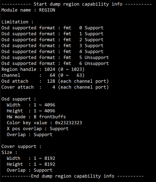
Record the current RGN usage status and device attributes, and can dynamically obtain information, which is convenient for debugging and testing.
Parameter Description
-
Region capability
- Region handle: The max regions to create are 1024, value range: [0~1023]
- channel: The max channels are 64, value range: [0~63]
- Osd attach: The max osds that can be bound to each channel of the output port are 128
- Cover attach: The max covers that can be bound to each channel of the output port are 4
- Overlay Supported Format: Overlay Supported Format
- 0:ARGB1555
- 1:ARGB4444
- 2:I2,align width by 4 pixels
- 3:I4,align width by 2 pixels
- 4:I8
- 5:RGB565
- 6:ARGB8888
- Osd Support:
- Width: Osd width value range: 1 ~ 4096
- Height: Osd height value range: 1 ~ 4096
- Color key value: Color key value: Default colorkey value of the system, except for the index format
- X pos overlap: X pos overlap: Support multiple OSDs overlapping in the x direction
- Overlap: Overlap: osd supports overlap or not
- HW mode: HW mode: The frontbuffs of Osd, currently se
- Cover support:
- Width: Osd width value range: 1 ~ 8192
- Height: Osd height value range: 1 ~ 8192
- Overlap: Overlap: Cover supports overlap or n
-
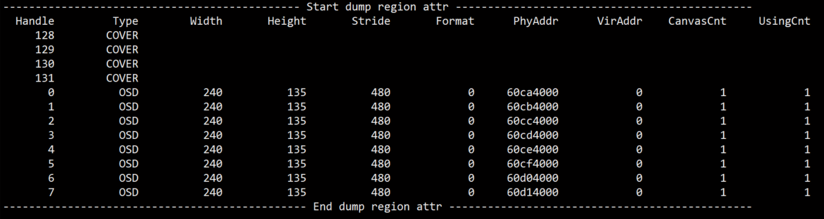
Region attr:
- Handle: Handle
- Type: Osd or Cover
- Width: Width
- Height: Height
- Stride: Stride
- Format: Color format [0-6]:ARGB1555,ARGB4444,I2,I4,I8,RGB565,ARGB8888
- VirAddr: Canvas virtual address
- PhyAddr: Canvas physical address
- CanvasCnt: Count of buffers currently used by Canvas
- UsingCnt: Use the current Canvas hw count
-
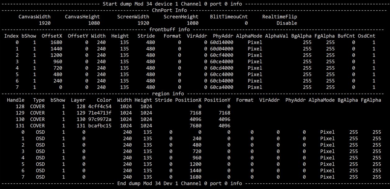
Channel Port Info:
- Frontbuffer info:
- Index: Frontbuffer index
- bShow: Show it or not
- OffsetX: X offset
- OffsetY: Y offset
- Width: Width
- Height: Height
- Stride: Stride
- Format: Color format
- VirAddr: Virtual address
- PhyAddr: Physical address
- AlphaMode: Alpha mode, pixel alpha or constant alpha
- AlphaVal: In constant alpha, alpha value
- BgAlpha: In pixel alpha, argb1555 background alpha
- FgAlpha: In pixel alpha, argb1555 foreground alpha
- BufCnt: Front buffers on the channel
- OsdCnt: Number of back buffers for splicing a front buffer on the channel
- Attach info:
- Handle: Handle of binding region
- Type: Type of binding region
- bShow: Show it or not
- Layer: Binding cover layer
- Color: Binding cover color
- Width: Width
- Height: Height
- Stride: Stride
- PositionX: X offset
- PositionY: Y offset
- Format: Color format of binding osd
- VirAddr: Virtual address
- PhyAddr: Physical address
- AlphaVal: In constant alpha, alpha value
- BgAlpha: In pixel alpha, argb1555 background alpha
- FgAlpha: In pixel alpha, argb1555 foreground alpha
- Frontbuffer info:
- Buffer info:
- kmalloc: Memory bytes allocated in the Region module
- mma alloc: Memory bytes allocated in the Region module through sys module
5.2. dumpRgnBuf
Function
Dump buffer of specified region
Command
echo dumpRgnBuf [Handle] [Path] > /proc/mi_modules/mi_rgn/mi_rgn0
Parameter Description
- [Handle]: region handle
- [Path]: Path to save dump data. The saved content is the canvas of the region.
Example
echo dumpRgnBuf 0 /mnt > /proc/mi_modules/mi_rgn/mi_rgn0
Generate file
Rgn0_canvasInfo_fmt0_64X48in /mnt.It is the canvas data of the region that the dump handle is 0, the color format is ARGB1555, the stride is 64, and the height is 48.
File format:
Rgn[Handle]_canvasInfo_fmt[Format]_[Stride]X[Height]
- [Handle]: region handle
- [Format]: Color format, ARGB1555 is 0, ARGB4444 is 1, I2 is 2, I4 is 3.
- [Stride]: Stride
- [Height]: Height
5.3. dumpFrontBuf
Function
Dump frontbuffer of specified channel and port.
Command
echo dumpFrontBuf [ModId] [DevId] [ChnID] [PortID] [Path] > /proc/mi_modules/mi_rgn/mi_rgn0
Parameter Description
- [ModId]: Module ID, refer to the module in mi_common_datatype.h to define enumeration values.
- [DevId]: Device id.
- [ChnID]: Channel id [0~63].
- [PortID]: Port id [0~3].
- [Path]: Path to save dump data. 0~2 files will be generated according to the actual frontbuffers currently used.
Example
echo dumpFrontBuf 34 1 0 0 /mnt > /proc/mi_modules/mi_rgn/mi_rgn0
Generate file
Mod34_Dev1_Chn0_Port0_frontbuf0_fmt0_64X48in /mnt. It is the data of the frontbuffer that the dump channel is 0, the output port is port 34, the index is 0, the color format is ARGB1555, the stride is 64, and the height is 48.File format:
Mod[ModId]_Dev[DevId]_Chn[Channel]_Port[Port]_frontbuf[Index]_fmt[Format]_[Stride]X[Height]
- [ModId]: Output module id
- [DevId]: Output device id
- [Channel]: Channel id
- [Port]: Output port
- [Index]: Frontbuffer index
- [Format]: Color format, ARGB1555 is 0, ARGB4444 is 1, I2 is 2, I4 is 3.
- [Stride]: Stride
- [Height]: Height
5.4. getcap
Function
Get region capability info.
Command
echo getcap > /proc/mi_modules/mi_rgn/mi_rgn0
5.5. dumprgn
Function
Get created region info.
Command
echo dumprgn > /proc/mi_modules/mi_rgn/mi_rgn0
5.6. dumpchport
Function
Get channel and port info.
Command
echo dumpchport > /proc/mi_modules/mi_rgn/mi_rgn0
5.7. bufcnt
Function
Get memory usage info.
Command
echo bufcnt > /proc/mi_modules/mi_rgn/mi_rgn0
5.8. dumpPalette
Function
Get Palette info.
Command
echo dumpPalette > /proc/mi_modules/mi_rgn/mi_rgn0
5.9. setDispOnOff
Function
Turn on or off a gwin.
Command
echo setDispOnOff [ModId] [DevId] [ChnID] [PortID] [Idx] [OnOff] > /proc/mi_modules/mi_rgn/mi_rgn0
Parameter Description
- [ModId]: Module ID, refer to the module in mi_common_datatype.h to define enumeration values.
- [DevId]: Device id
- [ChnID]: Channel id [0~63]
- [PortID]: Port id [0~3]
- [Idx]: The gwin number displayed by the osd on the current channel.
- [OnOff]: 0: OFF, 1: ON
Example
echo setDispOnOff 34 1 0 0 0 0 > /proc/mi_modules/mi_rgn/mi_rgn0
5.10. forceUpdate
Function
Force to update the back buffer of osd
Command
echo forceUpdate [handle] > /proc/mi_modules/mi_rgn/mi_rgn0
Parameter Description
- [handle]: Osd hander |
Example
echo forceUpdate 0 > /proc/mi_modules/mi_rgn/mi_rgn0
5.11. setFbListMaxCnt
Function
Set the number of front buffers to be displayed.
Command
echo setFbListMaxCnt [ModId] [DevId] [ChnID] [PortID] [SetByUsr] [Cnt] > /proc/mi_modules/mi_rgn/mi_rgn0
Parameter Description
- [ModId]: Module ID, refer to the module in mi_common_datatype.h to define enumeration values.
- [DevId]: Device id
- [ChnID]: Channel id [0~63]
- [PortID]: Port id [0~3]
- [SetByUsr]: Set by user or not, 1: Y; 0: N, default by system.
- [Cnt] If it is set by user, front buffer is used to display the number, after this setting, you can find it in BufCnt of Frontbuffer info.
Example
echo setFbListMaxCnt 34 1 0 0 1 3 > /proc/mi_modules/mi_rgn/mi_rgn0
5.12. setRealtimeFlip
Function
Enable the real-time OSD display mode to ensure that the OSD is displayed in the next video frame.
Command
echo setRealtimeFlip [ModId] [DevId] [ChnID] [PortID] [OnOff] > /proc/mi_modules/mi_rgn/mi_rgn0
Parameter Description
- [ModId]: Module ID, refer to the module in mi_common_datatype.h to define enumeration values.
- [DevId]: Device id
- [ChnID]: Channel id [0~63]
- [PortID]: Port id [0~3]
- [OnOff]: RealtimeFlip enable state
Example
echo setRealtimeFlip 34 1 0 0 1 >/proc/mi_modules/mi_rgn/mi_rgn0
5.13. setMaxCanvasForHandle
Function
Limit the maximum buffer number of specified handle.
Command
echo setMaxCanvasForHandle [handleId] [LimitNum] > /proc/mi_modules/mi_rgn/mi_rgn0
Parameter Description
- [handleId]: Handle Id
- [LimitNum]: The limited maximun buffer number
Example
echo setMaxCanvasForHandle 0 2 > /proc/mi_modules/mi_rgn/mi_rgn0
5.14. setMaxCanvasForPath
Function
Limit the maximum buffer number of specified channel and port.
Command
echo setMaxCanvasForPath [ModId] [DevId] [ChnID] [PortID] [LimitNum] > /proc/mi_modules/mi_rgn/mi_rgn0
Parameter Description
- [ModId]: Module ID, refer to the module in mi_common_datatype.h to define enumeration values.
- [DevId]: Device id
- [ChnID]: Channel id [0~63]
- [PortID]: Port id [0~3]
- [LimitNum]: The limited maximun buffer number
Example
echo setFbListMaxCnt 34 1 0 0 2 > /proc/mi_modules/mi_rgn/mi_rgn0